
Manual


71M6541 Demo Board REV 3.0 User’s Manual
3 Rev 4.0
2.3.5 Calibration Procedure with Five Measurements .............................................................................................. 42
2.3.6 Calibration Spreadsheets ................................................................................................................................ 42
2.3.7 Compensating for Non-Linearities ................................................................................................................... 45
2.4 Temperature Compensation ................................................................................................................................ 46
2.4.1 Error Sources .................................................................................................................................................. 46
2.4.2 Software Features for Temperature Compensation ........................................................................................ 47
2.4.3 Calculating Parameters for Compensation ...................................................................................................... 48
2.5 Testing the Demo Board ...................................................................................................................................... 51
2.5.1 Functional Meter Test ...................................................................................................................................... 51
2.6 Sensors and Sensor Placement .......................................................................................................................... 53
2.6.1 Self-Heating .................................................................................................................................................... 53
2.6.2 Placement of Sensors (ANSI) ......................................................................................................................... 54
2.6.3 Placement of Sensors (IEC) ............................................................................................................................ 55
2.6.4 Other Techniques for Avoiding Magnetic Crosstalk......................................................................................... 56
3 HARDWARE DESCRIPTION ................................................................................................................................. 58
3.1 71M6541-DB Description: Jumpers, Switches and Test Points ....................................................................... 58
3.2 Board Hardware Specifications .......................................................................................................................... 62
4 APPENDIX ............................................................................................................................................................. 64
4.1 71M6541-DB Electrical Schematic ...................................................................................................................... 65
4.2 71M6541-DB Bill of Material ................................................................................................................................. 67
4.3 71M6541-DB PCB Layout ..................................................................................................................................... 69
4.4 71M6541 Pinout Information ................................................................................................................................ 73
4.5 Revision History ................................................................................................................................................... 76
List of Figures
Figure 1-1: D6541 REV2.0 Demo Board with Debug Board: Basic Connections ................................................................ 7
Figure 1-2: HyperTerminal Sample Window with Disconnect Button (Arrow) ................................................................... 10
Figure 1-3: Port Speed and Handshake Setup (left) and Port Bit setup (right) .................................................................. 10
Figure 1-4: Typical Calibration Macro File ......................................................................................................................... 19
Figure 1-5: Emulator Window Showing Reset and Erase Buttons (see Arrows) ............................................................... 21
Figure 1-6: Emulator Window Showing Erased Flash Memory and File Load Menu ......................................................... 21
Figure 2-1: Shunt Connections.......................................................................................................................................... 34
Figure 2-2: Single-Phase Two-Wire Meter with Shunt Sensor .......................................................................................... 35
Figure 2-3: Single-Phase Two-Wire Meter with two Shunt Sensors .................................................................................. 35
Figure 2-4: Single-Phase Three-Wire Meter with two Shunt Sensors ............................................................................... 36
Figure 2-4: Watt Meter with Gain and Phase Errors. ......................................................................................................... 37
Figure 2-5: Phase Angle Definitions .................................................................................................................................. 40
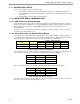
Figure 2-7: Calibration Spreadsheet for Three Measurements ......................................................................................... 43
Figure 2-8: Calibration Spreadsheet for Five Measurements ............................................................................................ 44
Figure 2-9: Non-Linearity Caused by Quantification Noise ............................................................................................... 45
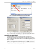
Figure 2-10: GAIN_ADJ over Temperature ........................................................................................................................ 49
Figure 2-11: GAIN_ADJ and GAIN_ADJ’ over Temperature .............................................................................................. 49
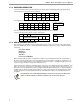
Figure 2-12: Meter with Calibration System ...................................................................................................................... 52
Figure 2-13: Calibration System Screen ........................................................................................................................... 52
Figure 2-14: Wh Load Lines at Room Temperature with 71M6201 and 50 µΩ Shunts ..................................................... 53
Figure 2-15: Typical Sensor Arrangement (left), Recommended Arrangement (right) ...................................................... 55
Figure 2-16: Improved Sensor Arrangement ..................................................................................................................... 55
Figure 2-17: Loop Formed by Shunt and Sensor Wire ...................................................................................................... 56
Figure 2-18: Shunt with Compensation Loop .................................................................................................................... 56