
Datasheet
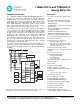


71M6541D/F/G and 71M6542F/G Data Sheet
4 Rev 4
6 Electrical Specifications ................................................................................................................. 139
6.1 Absolute Maximum Ratings ..................................................................................................... 139
6.2 Recommended External Components ..................................................................................... 140
6.3 Recommended Operating Conditions ...................................................................................... 140
6.4 Performance Specifications ..................................................................................................... 141
6.4.1 Input Logic Levels ........................................................................................................ 141
6.4.2 Output Logic Levels ..................................................................................................... 141
6.4.3 Battery Monitor............................................................................................................. 142
6.4.4 Temperature Monitor ................................................................................................... 142
6.4.5 Supply Current ............................................................................................................. 143
6.4.6 V3P3D Switch .............................................................................................................. 144
6.4.7 Internal Power Fault Comparators ............................................................................... 144
6.4.8 2.5 V Voltage Regulator – System Power ................................................................... 144
6.4.9 2.5 V Voltage Regulator – Battery Power .................................................................... 145
6.4.10 Crystal Oscillator .......................................................................................................... 145
6.4.11 Phase-Locked Loop (PLL) ........................................................................................... 145
6.4.12 LCD Drivers ................................................................................................................. 146
6.4.13 VLCD Generator .......................................................................................................... 147
6.4.14 VREF ........................................................................................................................... 149
6.4.15 ADC Converter............................................................................................................. 150
6.4.16 Pre-Amplifier for IAP-IAN ............................................................................................. 151
6.5 Timing Specifications ............................................................................................................... 152
6.5.1 Flash Memory .............................................................................................................. 152
6.5.2 SPI Slave ..................................................................................................................... 152
6.5.3 EEPROM Interface ...................................................................................................... 152
6.5.4 RESET Pin ................................................................................................................... 153
6.5.5 RTC .............................................................................................................................. 153
6.6 Package Outline Drawings....................................................................................................... 154
6.6.1 64-Pin LQFP Outline Package Drawing ...................................................................... 154
6.6.2 100-Pin LQFP Package Outline Drawing .................................................................... 155
6.7 Package Markings ................................................................................................................... 156
6.8 Pinout Diagrams ...................................................................................................................... 157
6.8.1 71M6541D/F/G LQFP-64 Package Pinout .................................................................. 157
6.8.2 71M6542F/G LQFP-100 Package Pinout .................................................................... 158
6.9 Pin Descriptions ....................................................................................................................... 159
6.9.1 Power and Ground Pins ............................................................................................... 159
6.9.2 Analog Pins .................................................................................................................. 160
6.9.3 Digital Pins ................................................................................................................... 161
6.9.4 I/O Equivalent Circuits ................................................................................................. 163
7 Ordering Information ...................................................................................................................... 164
7.1 71M6541D/F/G and 71M6542F/G ........................................................................................... 164
8 Related Information ........................................................................................................................ 164
9 Contact Information ........................................................................................................................ 164
Appendix A: Acronyms .......................................................................................................................... 165
Appendix B: Revision History ............................................................................................................... 166