
Datasheet

71M6541D/F/G and 71M6542F/G Data Sheet
12 Rev 4
transformers (CTs) and their corresponding signal conditioning circuits can be characterized and their
correction factors can be programmed to produce electricity meters with exceptional accuracy over the
industrial temperature range.
One of the two internal UARTs is adapted to support an Infrared LED with internal drive and sense configuration
and can also function as a standard UART. The optical output can be modulated at 38 kHz. This flexibility
makes it possible to implement AMR meters with an IR interface. A block diagram of the IC is shown in
Figure 1.
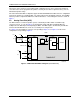
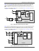
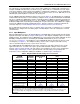
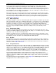
2.2 Analog Front End (AFE)
The AFE functions as a data acquisition system, controlled by the MPU. When used with locally
connected sensors, as seen in Figure 2, the analog input signals (IAP-IAN, VA and IBP-IBN) are
multiplexed to the ADC input and sampled by the ADC. The ADC output is decimated by the FIR filter
and stored in CE RAM where it can be accessed and processed by the CE.
See Figure 6 for the multiplexer sequence corresponding to Figure 2. See Figure 35 for the meter
configuration corresponding to Figure 2.
∆Σ
ADC
CONVERTER
VREF
MUX
VREF
VREF
VADC
22
FIR
IBP
IAP
VADC10 (VA)
IAN
IBN
71M6541
D/
F
CE RAM
*IN = Optional Neutral Current
Local
Shunt
IN*
CT
I
LINE
or
CT
11/5/2010
I
LINE
Figure 2. 71M6541D/F/G AFE Block Diagram (Local Sensors)