
Datasheet

71M6541D/F/G and 71M6542F/G Data Sheet
144 Rev 4
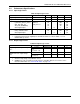
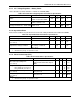
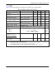
6.4.6 V3P3D Switch
Table 101: V3P3D Switch Performance Specifications
Parameter
Condition
Min
Typ
Max
Unit
On resistance – V3P3SYS to V3P3D
| I
V3P3D
| ≤ 1 mA
10
Ω
On resistance – VBAT to V3P3D
| I
V3P3D
| ≤ 1 mA,
VBAT>2.5V
10 Ω
V3P3D I
OH
, MSN
V3P3SYS = 3V
V3P3D = 2.9V
10 mA
V3P3D I
OH
, BRN
VBAT = 2.6V
V3P3D = 2.5V
10 mA
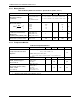
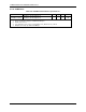
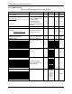
6.4.7 Internal Power Fault Comparators
Table 102. Internal Power Fault Comparator Specifications
Parameter
Condition
Min
Typ
Max
Unit
Overall response time
100mV overdrive, falling
100mV overdrive, rising
20
200
200
µs
µs
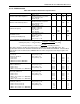
Falling Threshold
3.0 V Comparator
2.8 V Comparator
Difference 3.0V and 2.8V Comparators
V3P3 falling
2.83
2.75
50
2.93
2.81
136
3.03
2.87
220
V
V
mV
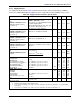
Falling Threshold
2.25 V Comparator
2.0 V Comparator
VDD (@VBAT=3.0V) – 2.25V Comparator
Difference 2.25V and 2.0V Comparators
VDD falling
2.2
1.90
0.25
0.15
2.25
2.00
0.35
0.25
2.5
2.20
0.45
0.35
V
V
V
V
Hysteresis,
(Rising Threshold - Falling Threshold)
3.0 V Comparator
2.8 V Comparator
2.25 V Comparator
2.0 V Comparator
T
A
= 22 °C
22
25
10
10
45
42
33
28
65
60
60
60
mV
mV
mV
mV
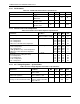
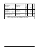
6.4.8 2.5 V Voltage Regulator – System Power
Table 103: 2.5 V Voltage Regulator Performance Specifications
Parameter
Condition
Min
Typ
Max
Unit
V2P5
V3P3 = 3.0 V - 3.8 V
ILOAD = 0 mA
2.55 2.65 2.75 V
V2P5 load regulation
VBAT = 3.3 V , V3P3 = 0 V
ILOAD = 0 mA to 1 mA
40 mV
Voltage overhead V3P3SYS-V2P5
I
LOAD
=
5 mA,
Reduce V3P3D until V2P5
drops 200 mV
440 mV