
Datasheet


71M6541D/F/G and 71M6542F/G Data Sheet
96 Rev 4
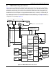
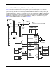
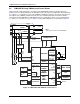
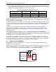
4.6 71M6542F/G Using 71M6x01 and Current Shunts
Figure 38 shows a typical two-phase connection for the 71M6542F/G using one isolated and one non-
isolated sensor. For best performance, the IAP-IAN current sensor input is configured for differential mode
(i.e., DIFFA_E = 1, I/O RAM 0x210C[4]). The 71M6x01 Isolated Sensor Interface is used to isolate phase B.
The outputs of the 71M6x01 Isolated Sensor Interface are routed through a pulse transformer, which is
connected to the pins IBP-IBN. The IBP-IBN pins must be configured for remote sensor communication
(i.e., RMT_E =1, I/O RAM 0x2709[3]). See Figure 5 for the AFE configuration corresponding to Figure 38.
MPU
RTC
TIMERS
IAP
VA
IBP
XIN
XOUT
RX
TX
TX
RX
COM0...5
V3P3A V3P3SYS
VBAT
VBAT_RTC
SEG
GNDA GNDD
SEG/DIO
DIO
ICE
PHASE A
NEUTRAL
LOAD
8888.8888
PULSES,
DIO
IR
AMR
POWER FAULT
COMPARATOR
MODUL-
ATOR
SERIAL PORTS
OSCILLATOR/
PLL
MUX and ADC
LCD DRIVER
DIO, PULSES
COMPUTE
ENGINE
FLASH
MEMORY
RAM
32 kHz
REGULATOR
Shunt
POWER SUPPLY
71M6542F/G
TEMPERATURE
SENSOR
VREF
BATTERY
PWR MODE
CONTROL
WAKE-UP
PHASE A
I
2
C or µWire
EEPROM
IAN
IBN
RTC
BATTERY
V3P3D
BATTERY
MONITOR
SPI INTERFACE
HOST
LCD DISPLAY
Resistor Dividers
Pulse
Trans-
former
71M6XX1
PHASE B
LOAD
VB
NEUTRAL
PHASE A
Shunt
Note:
This system is referenced to PHASE A
Figure 38: 71M6542F/G with 71M6x01 Isolated Sensor