
Manual


UG_1x22_052 73M1822/73M1922 Implementer’s Guide
Rev. 1.0 21
6 Interrupt Processing
During the course of operation the 73M1x22 can be expected to generate interrupts when errors or other
events occur that require immediate action. Each interrupt source corresponds to a bit in register 0x03.
This section will cover each interrupt and the appropriate actions to process it. The registers used in the
procedure are:
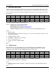
0x03 GPIO7 GPIO6 GPIO5 GPIO4 RGMON DET SYNL RGDT
Read ? ? ? ? ? ? ? ?
0x05 ENGPIO7 ENGPIO6 ENGPIO5 ENGPIO4 ENAPOL ENDET ENSYNL ENRGDT
Write X X X X 1 X X X
The temporary variables defined in the procedure are:
IntSrc = Interrupt sources (read from Register 0x03).
GPIO[7:4] bits indicate a GPIO Interrupt.
DET bit indicates a line condition error: DET Interrupt.
SYNL bit indicates a barrier failure: SYNL Interrupt.
RGMON and RGDT bits indicate a line signal detection: RGDT and RGMON Interrupts.
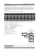
Begin
1. Wait for Interrupt.
2. Read Register 0x03 to determine the interrupt source(s), to clear the register value and de-assert the
INT pin (IntSrc = RG03).
3. Read RG05 (IntMsk = RG05.
4. Set ENAPOL = 1 (write xxxx_1xxx to RG05).
5. Process each interrupt source.
6. Re-enable interrupts set RG05 = IntMsk.
7. goto 1.
End
6.1 GPIO Interrupt
GPIO interrupts are a user dependent function controlled through the POL and ENGPIO registers.
Please refer to the 73M1822/73M1922 Data Sheet for their individual functionality. The functional
requirements of the software to handle a GPIO interrupt are user dependent.
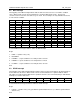
0x05
ENGPIO7
ENGPIO6
ENGPIO5
ENGPIO4
ENAPOL
ENDET
ENSYNL
ENRGDT
Write 1 1 1 X 1 X X X
0x06
POL7
POL6
POL5
POL4
Res
Res
Res
Res
Write 0/1 0/1 0/1 0/1 X X X X
Set the ENGPIO[7:5] bits of RG05 to enable the corresponding GPIO[7:4] interrupt(s).
Set the POL[7:4] bit of RG06 to the desired polarity.
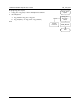
Begin
1. If GPIO7 or GPIO6 or GPIO5 or GPIO4= 1 (IntSrc[7:4] ≠ 0) then goto user defined GPIO Interrupt
Processing.
End