
Manual

73M1822/73M1922 Implementer’s Guide UG_1x22_052
6 Rev. 1.0
3 Device Configuration and Initialization
3.1 Host-Side Device (73M1902) Configuration
The Host-side device configuration and initialization includes the following steps:
1. Reset
2. First Interrupt
3. MAFE Interface Configuration
4. Clock and Sample Rate Management
3.1.1 Reset
Upon reset, the device will power up in the default state. See the 73M1822/73M1922 Data Sheet for
exact conditions of the default device state upon reset. The device will be ready within 100 μs after reset
and the user should not attempt to interact with the device before then.
3.1.2 First Interrupt
As the default device settings allow for the reporting of device interrupts, after reset, the device will report
an interrupt. The recommended way to deal with the first interrupt after reset is to ignore this interrupt
until the user is able to communicate on the AMFE interface. After MAFE communication has been
established it is recommended to disable the interrupt generation until the system is ready to handle
them.
Despite being in Register 0x05, ENAPOL is not an interrupt masking register and should not be
disabled.
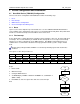
The registers used in this procedure are:
0x03 GPIO7 GPIO6 GPIO5 GPIO4 RGMON DET SYNL RGDT
Read X X X X X X X X
0x05 ENGPIO7 ENGPIO6 ENGPIO5 ENGPIO4 ENAPOL ENDET ENSYNL ENRGDT
Write
0 0 0 0 1 0 0 0
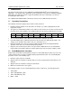
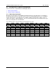
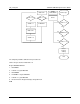
Begin
1. Release RST.
2. Wait for Interrupt.
3. Configure MAFE interface.
4. Set ENGPIO[7:4] = ENDET = ENSYNL = ENRGDT = 0, set ENAPOL = 1
(RG05 = 0x08).
5. Read RG03 to clear the register value and de-assert the INT pin.
End
Start
Release RST
INT?
No
Yes
Write RG05=0x08
Read
RG03=X
End