
Owner's manual


73M1866B/73M1966B Implementer’s Guide UG_1x66B_016
4 Rev. 1.3
1 Introduction
This guide describes how to use the 73M1866B and 73M1966B MicroDAA
®
FXO for Voice-over-IP (VoIP)
applications. The guide provides application-specific detail that is not found in the 73M1866B/73M1966B
Data Sheet. The guide also includes suggested algorithms that can be followed by users who are
developing their own software. In most cases the software implementations described are very similar, if
not the same, as those used in the Teridian 73M1x66B Reference Driver.
The 73M1966B and 73M1866B will be collectively referred to as the 73M1x66B in this document.
1.1 Procedure Conventions
The following conventions apply to the procedures in this document:
• Firmware/software variables in the procedures are in italics (e.g. VAL) to distinguish them from
register bits or fields.
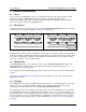
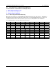
• The register is shown with the address in the leftmost cell of the first row. The first row shows the bit
mnemonic and is ordered with the most significant bit to the left and least significant bit to the right.
0x12
OFH
ENDC
ENAC
ENSHL
ENLVD
ENFEL
ENDT
ENNOM
Write 0/1 0 1 X 0 1 0 X
• The second row indicates values written in the indicated bits during the procedure.
• Cells with multiple values indicate that the bit is used more than once during the procedure. For
example, in the example above, OFH is first set to 0 and later set to 1.
• Register fields with an “X” in the procedures indicate bits that remain unchanged during write
operations or bits that are not relevant during read operations.
• Registers referenced in the procedures are represented as RGnn where nn is the hexadecimal
register address from 0x00 to 0x25 (for example, RG12 represents the register at address 0x12).
1.2 Read-Modify-Write Procedure
Register writes that include unchanged bits should use a read-modify-write procedure to preserve the
setting of bits that do not need to be modified during a given SPI transaction. The read-modify-write
procedure consists of the following steps:
1. Read the register value into a variable.
2. Apply a mask to the variable to retain bits that are not to be changed and clear bits that are to be
changed.
3. Apply a mask to the variable to change the desired bits.
4. Write the new value back to the register.
The following example uses the read-modify-write procedure to write 01xx_110x to Register 0xnn:
1. VAR = RGnn
2. VAR = VAR AND 0011_0001
3. VAR = VAR OR 0100_1100
4. RGnn = VAR