
Owner's manual


UG_1x66B_016 73M1866B/73M1966B Implementer’s Guide
Rev. 1.3 5
2 Hardware Requirements
2.1 Reset
The reset pin of the 73M1x66B is active low. Following the power-up of the device and the reset pin
being de-asserted, the 73M1x66B SPI interface is ready for communicating with the host.
Though not explicitly required, it is recommended that the PCM clock and FS be running and stable
before reset is de-asserted on the 73M1x66B device.
2.2 SPI Interface
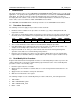
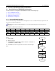
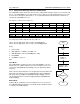
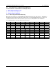
The SPI transactions are described in Section 5 of the 73M1866B/73M1966B Data Sheet. The write and
read transactions are illustrated in Figure 1 and Figure 2, respectively.
CONTROL ADDRESS DATA [7:0]
CSB
SCLK
SDI
SDO
HI-Z
CONTROL ADDRESS XXXXXXXX
CSB
SCLK
SDI
SDO
HI-Z
DATA [7:0]
Figure 1: SPI Write Transaction Figure 2: SPI Read Transaction
All SPI transactions that are targeting 73M1916 control registers (from address 0x12 to 0x19 and address
0x1F) must maintain a minimum inter-transaction gap of 500 μs. The inter-transaction gap starts from the
de-assertion of CSB after the data byte of the first transaction and terminates at the assertion of CSB
before the control byte of the second transaction.
2.3 PCM Interface
The PCM Highway Interface is described in Section 8 of the 73M1866B/73M1966B Data Sheet. The
PCM Highway Clock and Frame Sync signals must be stable and running at legal values for the
73M1x66B device to operate properly.
The settings that control the PCM Highway interface can be set via the SPI bus without a running PCLK
and FS.
See Section 3.1.4 PCM Interface Configuration for more information on how to properly configure the
PCM Highway interface.
2.4 Interrupts
The 73M1x66B devices provide a hardware interrupt pin (active low – open drain) that goes active upon
detection of any of several programmable hardware events within the 73M1x66B. The interrupt
functionality is described in Section 7.2 of the 73M1866B/73M1966B Data Sheet.
The interrupt pin is active and configured for operation upon reset of the 73M1x66B. Because interrupts
are enabled by default, the device will generate an interrupt as soon as reset is de-asserted (due to a
barrier failure detect). The host application must be ready to service or safely ignore this interrupt before
the de-assertion of reset. The recommended way to deal with the first interrupt after reset is to disable
the interrupt generation until the system is ready to handle them (see Section 3.1.1 Reset and Disable
Interrupts).