
Owner's manual


UG_1x66B_016 73M1866B/73M1966B Implementer’s Guide
Rev. 1.3 7
3.1.2 PCLK Clock Recovery and PLL Lock Detection
The 73M1x66B requires that the PLL be locked (to a stable PCLK and FS) to allow access to the line side
device. The 73M1x66B does not require the PLL to be locked (nor a stable PCLK and FS) to access the
host side device through the SPI interface. It is recommended that the PCLK and FS be stable before
releasing the 73M1x66B from reset.
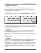
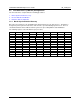
The registers used in this procedure are:
0x0F
ENFEH
PWDN
SLEEP
Res
Res
Res
Res
Res
Write
1 0 0/1 X X X X X
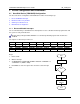
0x23
PCMEN
MASTER
PCODE[3:0]
LIN
LAW
Write X
VAL1 VAL2
X X
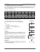
0x0D
LOKDET
SLHS
Res
Res
RSTLSBI
Res
Res
Res
Read ? X X X X X X X
The temporary variables defined in this procedure are:
VAL1 = System appropriate value to write to the MASTER bit.
VAL2 = System appropriate value to write to the PCODE[3:0] bits.
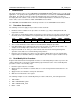
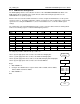
Begin
1. Release RST.
2. Write ENFEH = 1, PWDN = 0, SLEEP = 0.
3. Write MASTER = VAL1 and PCODE[3:0] = VAL2.
4. Read RG0D.
5. If LOKDET == 0 goto 5.
End
Slave Mode
If the 73M1x66B is configured for slave mode and PCODE is set to the
default value of 0, if PCLK and FS are present and stable before reset is
released the 73M1x66B will automatically lock to the appropriate PCLK
frequency.
If this cannot be achieved then the user should reset the PLL after PCLK and
FS have become stable before proceeding with further device initialization.
This can be done by toggling the SLEEP bit in Register 0x0F[5]. The user
can check that the PLL is locked and ready by polling the LOCKDET bit in
Register 0x0D[7].
Master Mode
In Master Mode, if PCLKI is present and stable before reset is released
the 73M1x66B will automatically lock to PCLKI and provide PCLK and FS
as outputs to the PCM Highway.
Start
ENFEH = 1
PWDN = 0
SLEEP = 0
MASTER = VAL1
PCODE = VAL2
LOCKDET==0
?
End
No
Yes
Release
RST