
Datasheet

DS_1x66B_001 73M1866B/73M1966B Data Sheet
Rev. 1.6 5
Tables
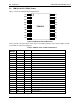
Table 1: 73M1906B 20-Pin TSSOP Pin Definitions .................................................................................. 8
Table 2: 73M1916 20-Pin TSSOP Pin Definitions
..................................................................................... 9
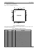
Table 3: 73M1906B 32-Pin QFN Pin Definitions
..................................................................................... 10
Table 4: 73M1916 32-Pin QFN Pin Definitions
....................................................................................... 12
Table 5: 73M1866B Pin Definitions
........................................................................................................ 14
Table 6: Isolation Barrier Characteristics
................................................................................................ 16
Table 7: Absolute Maximum Device Ratings
.......................................................................................... 16
Table 8: Recommended Operating Conditions
....................................................................................... 16
Table 9: DC Characteristics
................................................................................................................... 17
Table 10: SPI Interface Switching Characteristics
.................................................................................. 18
Table 11: Switching Characteristics – PCM Interface (Slave Mode)
........................................................ 19
Table 12: Switching Characteristics – PCM Interface (Master Mode)
...................................................... 19
Table 13: Reference Voltage Specifications
........................................................................................... 20
Table 14: Component Values for the Speaker Driver
.............................................................................. 21
Table 15: Call Progress Monitor Specification
........................................................................................ 22
Table 16: Line-Side Absolute Maximum Ratings
.................................................................................... 22
Table 17: VBG Specifications
................................................................................................................ 23
Table 18: Maximum DC Transmit Levels
................................................................................................ 23
Table 19: Transmit Path
......................................................................................................................... 24
Table 20: Receive Path
......................................................................................................................... 25
Table 21: Transmit Hybrid Cancellation Characteristics
.......................................................................... 26
Table 22: Receive Notch Filter
............................................................................................................... 26
Table 23: Over-voltage Detector
............................................................................................................ 27
Table 24: Over-current Detector
............................................................................................................. 27
Table 25: Under-voltage Detector
.......................................................................................................... 27
Table 26: Over-load Detector
................................................................................................................. 27
Table 27: Reference Bill of Materials for 73M1x66B
............................................................................... 30
Table 28: Reference Bill of Materials for Figure 14
................................................................................. 31
Table 29: Compatible Pulse Transformer Sources
................................................................................. 32
Table 30: Pulse Transformer Electrical Characteristics
........................................................................... 32
Table 31: Control and Status Register Map
............................................................................................ 37
Table 32: Alphabetical Bit Map
.............................................................................................................. 38
Table 33: PCM Control Functions
.......................................................................................................... 52
Table 34: Transmit Gain Control
............................................................................................................ 57
Table 35: Recommended Gain Setting
................................................................................................... 57
Table 36: Receive Gain Control
............................................................................................................. 59
Table 37: Barrier Control Functions
........................................................................................................ 61
Table 38: DAA Control Functions
........................................................................................................... 68
Table 39: Recommended Register Settings for International Compatibility
............................................. 72
Table 40: Line Sensing Control Functions
.............................................................................................. 75
Table 41: Loopback Modes
.................................................................................................................... 78
Table 42: Loopback Modes Summary
.................................................................................................... 79
Table 43: Order Numbers and Packaging Marks
.................................................................................... 87