
Datasheet


73S1215F Data Sheet DS_1215F_003
134 Rev. 1.4
Revision History
Revision Date Description
1.1 2/2/2007 First publication.
1.3 11/6/2007
On page 2, changed bullet from “ISO-7816 UART 9600 to 115kbps for
protocols T=0, T=1” to “ISO-7816 UART for protocols T=0, T=1”.
In Table 1, added Equivalent Circuit references.
In Table 3 and Table 5, removed the PREBOOT bit description.
In Section 1.4, updated program security description to remove pre-boot
and 32-cycle references.
In Section 1.4, changed the second bullet “Page zero of flash memory, the
preferred location for the user’s preboot code, may not be page-erased by
either MPT or ICE. Page zero may only be erased with global flash erase.
Note that global flash erase erases XRAM whether the SECURE bit is set
or not.” to “Page zero of flash memory may not be page-erased by either
MPU or ICE. Page zero may only be erased with global flash erase. Note
that global flash erase erases XRAM whether the SECURE bit is set or
not.”
In Section 1.7.1, changed “Mcount is configured in the MCLKCtl register
must be bound between a value of 1 to 7. The possible crystal or external
clock are shown in Table 12.“ to “Mcount is configured in the MCLKCtl
register must be bound between a value of 1 to 7. The possible crystal or
external clock frequencies for getting MCLK = 96MHz are shown in Table
12.”
In Table 12, removed the Mcount selections for 8, 9 and 10.
Added to the INT5Ctl description, “Note: The RTC based watchdog will be
enabled when set.”
In the BRCON description, changed “If BSEL = 1, the baud rate is derived
using timer 1.” to “If BSEL = 0, the baud rate is derived using timer 1.”
In Section 1.7.13, removed the following from the emulator port
description: “The signals of the emulator port have weak pull-ups. Adding
resistor footprints for signals E_RST, E_TCLK and E_RXTX on the PCB is
recommended. If necessary, adding 10KΩ pull-up resistors on E_TCLK
and E_RXTX and a 3KΩ on E_RST will help the emulator operate
normally if a problem arises.”
Changed last sentence of the DETTS bit description from “TS is decoded
prior to the FIFO and is stored in the receive FIFO,” to “TS is decoded
before being stored in the receive FIFO.”
In Section 1.7.15.1, added 230000 to the baud rate selections in bullet 7.
Changed the VDDFLT bit description to “If this bit is set = 0, the
CMDVCC3B and CMDVCC5B outputs are immediately set = 1 to signal to
the companion circuit to begin deactivation when there is a VDD Fault
event. If this bit is set = 1 and there is a VDD Fault, the firmware should
perform a deactivation sequence and then set CMDVCC3B or
CMDVCC5B = 1 to signal the companion circuit to set
VCC = 0.”
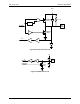
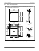
In Section 4, added equivalent circuit diagrams.
In Ordering Information, removed the leaded part numbers.