
Datasheet


DS_1215F_003 73S1215F Data Sheet
Rev. 1.4 9
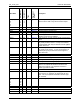
Pin Name
Pin (68 Qfn)
Pin (44 Qfn)
Type
Equivalent
Circuit*
Description
LED(3:0)
0
1
2
3
1
3
2
4
3
4
IO Figure 36 Special output drivers, programmable pull-down
current to drive LEDs. May also be used as inputs.
RXD 17 11 I Figure 33 Serial UART Receive data pin.
TXD 18 12 O Figure 30 Serial UART Transmit data pin.
INT3 51 I Figure 33 General purpose interrupt input.
INT2 52 32 I Figure 33 General purpose interrupt input.
SIO 50 31 IO Figure 29 IO data signal for use with external Smart Card
interface circuit such as 73S8024.
SCLK 48 30 O Figure 30 Clock signal for use with external Smart Card interface
circuit.
PRES 64 43 I Figure 41 Smart Card presence. Active high. Note: the pin has a
very weak pull down resistor. In noisy environments,
an external pull down may be desired to insure against
a false card event.
PRES 56 35 I Figure 42 Smart Card presence. Active low. Note: the pin has a
very weak pull up resistor. In noisy environments, an
external pull up may be desired to insure against a
false card event.
CLK 57 36 O Figure 39 Smart card clock signal.
RST 59 38 O Figure 39 Smart card Reset signal.
IO 63 42 IO Figure 40 Smart card Data IO signal.
AUX1 62 41 IO Figure 40 Auxiliary Smart Card IO signal (C4).
AUX2 61 40 IO Figure 40 Auxiliary Smart Card IO signal (C8).
VCC 60 39 PSO
Smart Card VCC supply voltage output. A 0.47μF
capacitor is required and should be located at the
smart card connector. The capacitor should be a
ceramic type with low ESR.
GND 58 37 GND Smart Card Ground.
VPC 55 34 PSI Smart Card LDO regulator power supply source. A
10μF and a 0.1μF capacitor are required at the VPC
input. The 10μF capacitor should be a ceramic type
with low ESR.
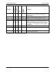
TBUS(3:0)
0
1
2
3
53
49
47
43
IO
Trace bus signals for ICE.
RXTX 45 28 IO ICE control.
ERST 40 25 IO ICE control.
ISBR 68 IO ICE control.
TCLK 41 26 I ICE control.