
Datasheet


73S8010C Data Sheet DS_8010C_024
6 Rev. 1.5
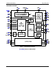
1.4 Microcontroller Interface
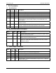
Name
PIN
(SO)
PIN
(QFN)
Description
INT 23 22
Interrupt output (negative assertion): Interrupt output signal to the
processor. A 20 kΩ pull up to V
DD
is provided internally.
PWRDN 8 5
Power Down control input: Active High. When Power Down (PD) mode is
activated, all internal analog functions are disabled to place the 73S8010C
in its lowest power consumption mode. Must be tied to ground when the
power down function is not used.
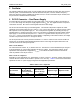
SAD0
SAD1
SAD2
1
2
3
29
30
31
Serial device address bits: Digital inputs for address selection that allow
the connection of up to 8 devices in parallel. Address selections as follows:
SAD2 SAD1 SAD0 I
2
C Address (7 bits)
0 0 0 0x40
0 0 1 0x42
0 1 0 0x44
0 1 1 0x46
1 0 0 0x48
1 0 1 0x4A
1 1 0 0x4C
1 1 1 0x4E
Pins SAD0 and SAD1 are internally pulled-down and SAD2 is
internally pulled-up.
The default address when left unconnected is 48h.
SCL 19 18 I
2
C clock signal input.
SDA 20 19 I
2
C bi-directional serial data signal.
I/OUC 26 26
System controller data I/O to/from the card. Includes internal pull-up
resistor to V
DD.
AUX1UC 27 27
System controller auxiliary data I/O to/from the card. Includes internal pull-
up resistor to V
DD.
AUX2UC 28 28
System controller auxiliary data I/O to/from the card. Includes internal pull-
up resistor to V
DD.