
Datasheet


73S8010C Data Sheet DS_8010C_024
8 Rev. 1.5
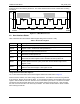
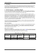
ACK bit is sent to the master by the device. The master should send the STOP condition after receiving
the ACK bit.
Figure 2: I
2
C Bus Write Protocol
2.2 Host Interface Status
Table 3 describes the Host Interface Status Register bits (power-on Reset = 0x04).
Table 3: Host Status Register
Name Bit Description
PRES 0 Set when the card is present; reset when the card is not present.
PRESL 1
Set when the PRES pin changes state (rising/falling edge); reset when the status
register is read. Generates an interrupt when set
I/O 2 Set when I/O is high; reset when I/O is low.
SUPL 3
Set when a voltage fault is detected; reset when the status register is read.
Generates an interrupt when set.
PROT 4
Set when an over-current or over-heating fault has occurred during a card session;
reset when the status register is read. Generates an interrupt when set.
MUTE 5
Set during ATR when the card has not answered during the ISO 7816-3 time
window (40000 card clock cycles); reset when the next session begins or this
register is read.
EARLY 6
Set during ATR when the card has answered before 400 card clock cycles; reset
when the next session begins or this register is read.
ACTIVE 7 Set when the card is active (V
CC
is on); reset when the card is inactive.
I
2
C-bus Read from the Status Register:
The I
2
C-bus Read Command from the Status Register follows the format shown in Figure 3.
After the START condition, the master sends a slave address. This address is seven bits long followed
by an eighth bit, which is the opcode bit (R/W). A ‘one’ indicates the master will read data from the status
register. After the R/W bit, the ’zero’ ACK bit is sent to the master by the device. The device now starts
sending the 8-bit status register data to the control register during the DATA bits time. After the DATA
bits, the ‘one’ ACK bit is sent to the device by the master. The master should send the STOP condition
after receiving the ACK bit.