78M6610+PSU Evaluation Kit User Manual April 2013 Rev 2 Maxim Integrated cannot assume responsibility for use of any circuitry other than circuitry entirely embodied in a Maxim Integrated product. No circuit patent licenses are implied. Maxim Integrated reserves the right to change the circuitry and specifications without notice at any time. Maxim Integrated 160 Rio Robles, San Jose, CA 95134 USA 1-408-601-1000 © 2013 Maxim Integrated Products, Inc.
78M6610+PSU Evaluation Kit User Manual Table of Contents 1 Introduction ......................................................................................................................................... 4 1.1 Ordering Information .................................................................................................................. 4 1.2 Package Contents...................................................................................................................... 4 1.
78M6610+PSU Evaluation Kit User Manual Figures Figure 1: 78M6610+PSU Evaluation Kit Application Diagram .............................................................................. 5 Figure 2: 78M6610+PSU Evaluation Board .......................................................................................................... 9 Figure 3: 78M6610+PSU Evaluation Kit Connections ..........................................................................................
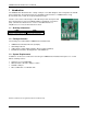
78M6610+PSU Evaluation Kit User Manual 1 Introduction The 78M6610+PSU Evaluation Kit is a design example of a modular daughter card for integration into AC-DC power-supply units. The kit demonstrates the capabilities and performance of 78M6610+PSU energy measurement device in both the 16-pin and 24-pin packages. The kit is connected to a PC through a USB cable that provides both power and data communication to the board.
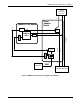
78M6610+PSU Evaluation Kit User Manual 120/240V Single Phase AC Source J1 78M6610+PSU Board J3 Shunt Adaptor Board 5V Voltage Divider J2 J4 DC/DC USB Controller Line Earth Gnd 78M6610 +PSU Current Shunt Neutral Isolation 3V3 Reg J11 USB Host PC Load Under Test Figure 1: 78M6610+PSU Evaluation Kit Application Diagram Rev 2 5
78M6610+PSU Evaluation Kit User Manual 1.4 Safety and ESD Notes EXERCISE CAUTION WHEN LIVE AC VOLTAGES ARE PRESENT! Standard ESD precautions must be taken when handling electronic equipment. The 78M6610+PSU contains ESD protected interfaces. Do not connect test equipment or external development boards directly to the 78M6610+PSU hardware. Damage to the 78M6610+PSU and external equipment will occur due to the 78M6610+PSU’s “high side” reference topology. The 78M6610+PSU’s V3P3 supply rail (i.e.
8M6610+PSU Evaluation Kit User Manual 2 Installation 2.1 USB Driver Installation This Evaluation Kit includes an isolated USB interface for serial communications with a PC. The FTDI USB controller IC FT232R performs the USB functions. The FTDI Windows driver presents a virtual COM port for enabling serial communications. The FTDI Windows driver is a certified driver for Windows XP and Windows 7.
78M6610+PSU Evaluation Kit User Manual • The System Properties screen appears. Click on the Hardware tab. Click on Device Manager. Under Ports (COM & LPT), look for the USB Serial Port assignment. • Take note of the COM port assignment for the USB Serial Port. COM Port: 2.2.1 FTDI COM Port Trouble Shooting If the FTDI device driver did not install properly, there would be no assigned COM port number for the FTDI controller. Repeat the USB Driver Installation, see Section 2.1.
78M6610+PSU Evaluation Kit User Manual 2.3 Basic Connection Setup Figure 1 shows the basic connections of the 78M6610+PSU Evaluation Kit for use with external equipment. The shunt adaptor board consists of the host side components necessary for the evaluation environment that would be replaced by the target system. This host board provides a USB serial UART controller, serial interface DC-DC power isolator, a current shunt, and AC wiring terminals.
78M6610+PSU Evaluation Kit User Manual Attach an AC source and AC load to the Shunt Adaptor Board as shown below. Connect J1 and J3 to an external AC power source. Connect J2 and J4 to the load to be measured. The 78M6610+PSU Evaluation Kit hardware is designed for 120 VAC and 230 VAC (nominal) up to 300 VAC (max).
78M6610+PSU Evaluation Kit User Manual 2.4 Jumper and Switch Settings The following tables describe the 78M6610+PSU Evaluation Kit jumpers and switches and their setting for different configurations.
78M6610+PSU Evaluation Kit User Manual Table 3: Shunt Adaptor Board Connector Descriptions 12 Schematic and Silkscreen Reference Description J1 AC Neutral to Source J2 AC Neutral to Load J3 AC Line to Source J4 AC Line to Load J5 AC Earth GND to Source J6 AC Earth GND to Load J7 Sensor connector to 78M6610+PSU Evaluation Board J9 Optional UART communications connector J10 USB controller TX jumper. Default = Installed Remove when using J9.
78M6610+PSU Evaluation Kit User Manual 3 Graphical User Interface (GUI) A graphical user interface (GUI) is included on the 78M6610+PSU Evaluation Kit CD to facilitate quick evaluation of the 78M6610+PSU energy measurement device. The GUI requires Microsoft.NET Framework 4 on the PC for which the GUI is to execute on. Upon invoking the GUI executable file, an installation wizard may appear if Microsoft.NET Framework 4 is not installed on the PC.
78M6610+PSU Evaluation Kit User Manual 4 Schematics, Bill of Materials, and PCB Layouts This section includes the schematics, bill of materials, and PCB layouts for the 78M6610+PSU Evaluation Boards and the Shunt Adaptor Board. 4.1 78M6610+PSU 16-Pin Evaluation Board Schematics . 3.3V COMM 5V C2 0.1uF 0603 VOUT EN NC R13 500 0603 5 4 C3 4.7uF 0805 C4 0.1uF 0603 C5 0.1UF 0603 R17 150 0603 R15 360 0603 TCMT1107 U5 1 C1 4.7uF 0805 VIN 1 3 4 1 1 2 GND J2 2 5V COMM 5V 3.
78M6610+PSU Evaluation Kit User Manual 4.2 78M6610+PSU 16-Pin Evaluation Board Bill of Materials Table 4: 78M6610+PSU 16-Pin Evaluation Board Bill of Materials Rev 2 Item Q Reference Part PCB Footprint Part Number Manufacturer RoHS-6 1 2 C1,C3 4.7uF 805 C2012Y5V1C475Z/0.85 TDK Yes 2 7 C2,C4,C5,C17 0.
78M6610+PSU Evaluation Kit User Manual 4.
78M6610+PSU Evaluation Kit User Manual Figure 7: 78M6610+PSU 16-Pin Evaluation Board PCB Bottom View Rev 2 17
78M6610+PSU Evaluation Kit User Manual 4.4 78M6610+PSU 24-Pin Evaluation Board Schematics . 3.3V COMM 5V U1 MC78PC33 SOT23-5 TP15 22 23 4 HEADER 750 0603 1 2 3 Connection for external 10K NTC Thermistor 3.3V D1 8 ATEMP1 ATEMP2 t 3.3V Vin Ext GREEN or BLUE 9 10 Y1 1 3 C8 0603 10K R14 0603 1 TP11 DNP TP 1 TP12 DNP TP 1 TP13 DNP TP RED 0603 R24 220 D3 /ACFAULT CON2 TCMT1107 U8 J14 2 1 R12 0603 15K CON2 3.
78M6610+PSU Evaluation Kit User Manual 4.5 78M6610+PSU 24-Pin Evaluation Board Bill of Materials Table 5: 78M6610+PSU 24-Pin Evaluation Board Bill of Materials Item Q 1 2 C1,C3 4.7uF 805 C2012Y5V1C475Z/0.85 TDK Yes 2 8 C2,C4,C5,C12,C17 0.
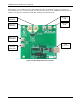
78M6610+PSU Evaluation Kit User Manual Figure 9: 78M6610+PSU 24-Pin Evaluation Board PCB Top View 20 Rev 2
78M6610+PSU Evaluation Kit User Manual Figure 10: 78M6610+PSU 24-Pin Evaluation Board PCB Bottom View Rev 2 21
78M6610+PSU Evaluation Kit User Manual 4.6 Shunt Adaptor Board Schematics . Isolated DC/DC Male NEMA 5-15 . J1 STERM VR1 VBT1-5V NEUTRAL R1 0.004 1% 2.5W 2512P VIN VOUT VGND GND 2 USB5P 1 C6 0.1uF 0603 C5 4.7uF 1206P 8 7 6 3 C4 4.7uF 1206P R2 0 0603 NC4 NC3 NC2 NC1 5 4 CURRENT INPUT 1 2 3 4 ISO5V NEUTRAL 1 2 3 4 Isolated +5V LOAD_RETURN J13 J2 STERM USBGND ISOGND 2 1 USB5P FEMALE CON2 UTX URX USBGND 1 2 3 4 J9 J3 STERM 1.
78M6610+PSU Evaluation Kit User Manual 4.7 Shunt Adaptor Board Bill of Materials Table 6: Shunt Adaptor Board Bill of Materials Item Q Reference Part PCB Footprint Part Number Manufacturer RoHS-6 1 2 C2,C6 0.1uF 0603 C0603C104K5RACTU Kemet Yes 2 3 C3,C4,C5 4.7uF 1206P C3216Y5V1C475Z/0.85 TDK Yes 3 4 G1,G2,G3,G4 MTHOLE MTGPS.
78M6610+PSU Evaluation Kit User Manual 4.
78M6610+PSU Evaluation Kit User Manual Figure 13: Shunt Adaptor Board PCB Bottom View Rev 2 25
78M6610+PSU Evaluation Board User Manual 5 Included Documentation The following 78M6610+PSU documents are included on the CD: 78M6610+PSU Data Sheet 78M6610+PSU Evaluation Kit User Manual 6 Contact Information For more information about Maxim products or to check the availability of the 78M6610+PSU, contact technical support at www.maximintegrated.com/support. Revision History Revision Date Description 0 7/25/2012 First publication. 1 8/17/2012 Expanded GUI initialization instructions. 1.