
Datasheet


78M6612 Data Sheet DS_6612_001
8 Rev 2
1.2 Analog Front End (AFE)
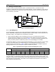
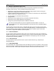
The AFE functions as a data acquisition system, controlled by the MPU. It consists of an input
multiplexer, a delta-sigma A/D converter, and a voltage reference. The main signals (IA, VA, IB, VB) are
sampled and the ADC counts obtained are stored in CE DRAM where they can be accessed by the CE
and, if necessary, by the MPU.
Figure 2: AFE Block Diagram
1.2.1 Input Multiplexer
The input multiplexer supports up to four input signals that are applied to pins IA, VA, IB, and VB of the
device. Additionally, using the alternate multiplexer selection, it has the ability to select temperature and
the battery voltage. The multiplexer can be operated in two modes:
• During a normal multiplexer cycle, the signals from the IA, IB, VA, and VB pins are selected.
• During the alternate multiplexer cycle, the temperature signal (TEMP) and the battery monitor are
selected, along with the signal sources shown in Table 1. To prevent unnecessary drainage on the
battery, the battery monitor is enabled only with the BME bit (0x2020[6]) in the I/O RAM.
The alternate multiplexer cycles are usually performed infrequently (e.g. every second or so) by the MPU.
In order to prevent disruption of the voltage tracking PLL and voltage allpass networks, VA is not
replaced in the ALT mux selections. Table 1 details the regular and alternative multiplexer sequences.
Missing samples due to an ALT multiplexer sequence are filled in by the CE.
Table 1: Inputs Selected in Regular and Alternate Multiplexer Cycles
Regular MUX Sequence ALT MUX Sequence
Mux State
Mux State
EQU
0
1
2
3
0
1
2
3
2 IA VA IB VB TEMP VA VBAT VB
In a typical application, IA and IB are connected to current sensors that sense the current on each branch
of the line voltage. VA and VB are typically connected to voltage sensors through resistor dividers. The
multiplexer control circuit is clocked by CK32, the 32.768 kHz clock from the PLL block, and launches with
each new pass of the CE program. The duration of each multiplexer state depends on the number of
ADC samples processed by the FIR.
IA
VA
MUX
VREF
4.9MHz
VBIAS
CROSS
CK32
VREF
VREF_DIS
MUX
CTRL
MUX_DIV
CHOP_E
EQU
IB
MUX
MUX_ALT
V3P3A
FIR_LEN
FIR
VB
VBIAS
VREF_CAL
∆Σ ADC
CONVERTER
+
-
VREF
ADC_E
TEMP
VBAT
FIR_DONE
FIR_START