
Datasheet


DS1023
8 of 16
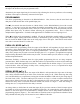
DALLAS SEMICONDUCTOR TEST CIRCUIT Figure 8
TEST SETUP DESCRIPTION
Figure 8 illustrates the hardware configuration used for measuring the timing parameters of the DS1023.
The input waveform is produced by a precision pulse generator under software control. Time delays are
measured by a time interval counter (20 ps resolution) connected to the output. The DS1023 serial and
parallel ports are controlled by interfaces to a central computer. All measurements are fully automated
with each instrument controlled by the computer over an IEEE 488 bus.
TEST CONDITIONS
INPUT:
Ambient Temperature: 25°C ± 3°C
Supply Voltage (V
CC
): 5.0V ± 0.1V
Input Pulse: High = 3.0V ± 0.1V
Low = 0.0V ± 0.1V
Source Impedance: 50 ohms max.
Rise and Fall Time: 3.0 ns max.
(measured between
0.6V and 2.4V)
Pulse Width: 500 ns
Period: 1 ms
NOTE: Above conditions are for test only and do not restrict the operation of the device under other data
sheet conditions.
OUTPUT:
Output is loaded with a 74F04. Delay is measured between the 1.5V level of the rising edge of the input
signal and the 1.5V level of the corresponding edge of the output.