
Datasheet


DS1077
5 of 21
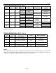
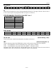
SHUTDOWN CONTROL WITH PDN0 AND PDN1 Table 3
PDN0
(BIT)
PDN1
(BIT)
SHUTDOWN CONTROL
0 0 NONE*
0 1 CTRL1
1 0 CTRL0
1 1 CTRL0 OR CTRL1
*CTRL0 performs a power-down if SEL0 and EN0 are both 0 (see Table 1).
REGISTER FUNCTIONS
The user programmable registers can be programmed by the user to determine the mode of operation
(MUX), operating frequency (DIV), and bus settings (BUS). Details of how these registers are
programmed can be found in a later section; in this section the functions of the registers are described.
The register settings are nonvolatile, the values being stored automatically or as required in EEPROM
when the registers are programmed via the SDA and SCL pins.
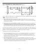
MUX WORD
MSB LSB MSB LSB
Name * PDN1 PDN0 SEL0 EN0 0M1 0M0 1M1 1M0 DIV1 - - - - - -
Default
setting
0 0 0 1 1 0 0 0 0 0 x x x x x x
first data byte second data byte
*This bit must be set to zero.
DIV1 (bit)
This bit allows the output of the Prescaler P1 to be routed directly to the OUT1 pin (DIV1 = 1). The N
divider is bypassed so the programmed value of N is ignored. If DIV1 = 0 (default) the N divider
functions normally.
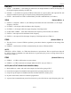
0M1, 0M0, 1M1, 1M0 (bits)
These bits set the prescalers P0 and P1, to divide by 1, 2, 4, or 8 (see Table 4).
PRESCALER DIVISOR M SETTINGS Table 4
0M1 0M0
Prescaler
P0 Divisor
“M”
1M1 1M0
Prescaler
P1 Divisor
“M”
0 0
1**
0 0
1**
0 1 2 0 1 2
1 0 4 1 0 4
1 1 8 1 1 8
**Default Condition