
Datasheet


DS1077
7 of 21
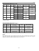
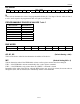
DIV WORD
MSB LSB MSB LSB
N9 N8 N7 N6 N5 N4 N3 N2 N1 N0 X X X X X X
first data byte second data byte
N
These ten bits determine the value of the programmable divider (N). The range of divisor values is from 2
to 1025, and is equal to the programmed value of N plus 2 (see Table 5).
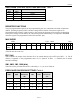
PROGRAMMABLE DIVISOR N VALUES Table 5
BIT VALUE DIVISOR (N)
0 000 000 000** 2
0 000 000 001 3
- -
- -
- -
- -
1 111 111 111 1025
**Default Condition
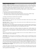
BUS WORD
Name - - - - WC A2 A1 A0
Factory Default 0* 0* 0* 0* 0 0 0 0
*These bits are reserved and must be set to zero.
A0, A1, A2
(Default Setting = 000)
These are the device select bits that determine the address of the device.
WC (Default Setting WC = 0)
This bit determines when/if the EEPROM is written to after register contents have been changed.
If WC = 0 the EEPROM is written automatically after a write register command.
If WC = 1 the EEPROM is only written when the “WRITE ” command is issued.
Regardless of the value of the WC bit, when the BUS register (A0, A1, A2) is written, the current value in
all registers (DIV, MUX, and BUS) are immediately written to the EEPROM.