
Datasheet


DS1077
4 of 21
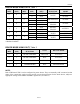
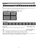
DEVICE MODE USING OUT0 Table 1
EN0
(BIT)
SEL0
(BIT)
PDN0
(BIT)
CTRL0
(PIN)
OUT0
(PIN)
CTRL0
FUNCTION
DEVICE
MODE
1 HI-Z POWER-DOWN
0 0 0
0 HI-Z
POWER-
DOWN*
ACTIVE
1 MCLK/M
0 1 0
0 MCLK
MUX SELECT ACTIVE
1 HI-Z
1 0 0
0 MCLK
OUTPUT
ENABLE
ACTIVE
1 HI-Z
1 1 0
0 MCLK/M
OUTPUT
ENABLE
ACTIVE**
1 HI-Z POWER-DOWN
X 0 1
0 MCLK
POWER-
DOWN
ACTIVE
1 HI-Z POWER-DOWN
X 1 1
0 MCLK/M
POWER-
DOWN
ACTIVE
*This mode is for applications where OUT0 is not used, but CTRL0 is used as a device shutdown.
**Default Condition
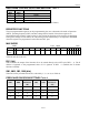
DEVICE MODE USING OUT1 Table 2
PDN1
(BIT)
CTRL1
(PIN)
CTRL1
FUNCTION
OUT1 DEVICE MODE
0 0 OUTPUT ENABLE OUT CLK ACTIVE**
0 1 OUTPUT ENABLE HI-Z ACTIVE**
1 0 POWER-DOWN OUT CLK ACTIVE
1 1 POWER-DOWN HI-Z POWER-DOWN
**Default Condition
NOTE:
Both CTRL0 and CTRL1 can be configured as power-downs. They are internally “OR” connected so that
either of the control pins can be used to provide a power-down function for the whole device, subject to
appropriate settings of the PDN0 and PDN1 register bits (see Table 3).