
Datasheet


Spread-Spectrum Crystal Multiplier
Maxim Integrated 3
DS1080L
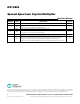
AC ELECTRICAL CHARACTERISTICS
(V
CC
= +3.0 to +3.6V, T
A
= -40°C to +125°C, unless otherwise noted.)
PARAMETER SYMBOL CONDITIONS MIN TYP MAX UNITS
Measured at V
CC
/2, CMSEL = 0 or open 40 60
SSO Duty Cycle SSODC
Measured at V
CC
/2, CMSEL = 1 30 70
%
Rise Time t
R
(Note 6) 1.6 ns
Fall Time t
F
(Note 6) 1.6 ns
Peak Cycle-to-Cycle Jitter t
J
f
SSO
= 16MHz, T
A
= -40 to +85°C,
10,000 cycles (N ote 5)
75 ps
16MHz 20
Power-Up Time t
POR
PDN pin (Note 7)
33.4MHz 11
ms
Power-Down Time t
PDN
PDN pin (Notes 8 and 9) 100 ns
Dither R ate f
DITHER
(Note 9) f
IN
/992
Note 1: All voltages referenced to ground.
Note 2: Maximum source/sink current applied to input to be considered an open. Typical voltage range between 0.4 x V
CC
and 0.55
x V
CC
.
Note 3: Applicable to pins CMSEL, SMSEL, and PDN.
Note 4: See information about C
L1
and C
L2
in the
Applications Information
section at the end of the data sheet.
Note 5: Not production tested.
Note 6: For 7pF load.
Note 7: Time between PDN deasserted to output active.
Note 8: Time between PDN asserted to output high impedance.
Note 9: Guaranteed by design.