
Datasheet


Spread-Spectrum Crystal Multiplier
Maxim Integrated 7
DS1080L
Layout Considerations
As noted earlier, the crystal should be placed very
close to the device to minimize excessive loading due
to parasitic capacitances. Care should also be taken to
minimize loading on pins that could be open as a pro-
gramming option (SMSEL and CMSEL). Coupling on
inputs due to clocks should be minimized.
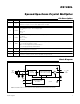
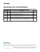
X2
NOTE: IN THE ABOVE CONFIGURATION WITH PDN CONNECTED TO V
CC
, SMSEL CONNECTED TO GND
AND CMSEL OPEN, THE DEVICE IS IN NORMAL OPERATION WITH 2x CLOCK MULTIPLICATION, AND
SPREAD-SPECTRUM MAGNITUDE OF ±0.5%.
f
SSO
V
CC
V
CC
V
CC
SSO
PDN
X1
CRYSTAL
C
L1
C
L2
DECOUPLING
CAPACITOR
GND
CMSEL
SMSEL
8
7
6
5
1
2
3
4
DS1080L
Typical Operating Circuit
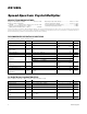
Package Information
For the latest package outline information and land patterns
(footprints), go to www.maximintegrated.com/packages. Note
that a “+”, “#”, or “-” in the package code indicates RoHS status
only. Package drawings may show a different suffix character,
but the drawing pertains to the package regardless of RoHS status.
PACKAGE
TYPE
PACKAGE
CODE
OUTLINE
NO.
LAND
PATTERN NO.
8 µSOP U8+1
21-0036 90-0092