
Datasheet

DS1085L
18 of 21
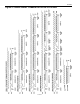
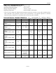
AC ELECTRICAL CHARACTERISTICS: 2-WIRE INTERFACE
(V
CC
= 3.3V ±10%, T
A
= 0°C to +70°C.)
PARAMETER SYMBOL CONDITION MIN TYP MAX UNITS NOTES
Fast mode 400
SCL Clock Frequency f
SCL
Standard mode 100
kHz
14
Fast mode 1.3
Bus Free Time Between
a STOP and START
Condition
t
BUF
Standard mode 4.7
ms
Fast mode 0.6 Hold Time (Repeated)
START Condition
t
HD:STA
Standard mode 4.0
ms
11
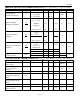
Fast mode 1.3
LOW Period of SCL t
LOW
Standard mode 4.7
ms
Fast mode 0.6
HIGH Period of SCL t
HIGH
Standard mode 4.0
ms
Fast mode 0.6 Setup Time for a
Repeated START
t
SU:STA
Standard mode 4.7
ms
Fast mode 0
Data Hold Time t
HD:DAT
Standard mode 0
0.9
ms
12, 13
Fast mode 100
Data Setup Time t
SU:DAT
Standard mode 250
ns 14
Fast mode 300 Rise Time of Both SDA
and SCL Signals
t
R
Standard mode
20 + 0.1C
B
1000
ns 15
Fast mode 300 Fall Time of Both SDA
and SCL Signals
t
F
Standard mode
20 + 0.1C
B
1000
ns 15
Fast mode 0.6
Setup Time for STOP t
SU:STO
Standard mode 4.0
ms
Capacitive Load for
Each Bus Line
C
B
400 pF 15
NV Write-Cycle Time t
WR
10 ms 16
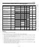
NOTES:
1) All voltages are referenced to ground.
2) This is the absolute accuracy of the output frequency at the default settings.
3) This is the percent frequency change that is observed in output frequency with changes in voltage
from nominal voltage at a temperature of T
A
= +25°C.
4) This is the percentage frequency change from the +25°C frequency due to temperature at a nominal
voltage of 3.3V.
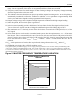
5) The maximum temperature change varies with the master frequency setting. The minimum occurs at
the default master frequency (f
default
). The maximums occur at the extremes of the master oscillator
frequency range (33MHz or 66MHz) (see Figure 5).
6) The integral nonlinearity of the frequency adjust DAC is a measure of the deviation from a straight
line drawn between the two endpoints of a range.