
Datasheet
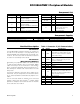


DESIGNATION QTY DESCRIPTION
J3 1 5-pin straight male header
R1, R2, R8,
R9, R10
5
4.7kI Q5% resistors (0603)
R3, R4, R5 3
1kI Q5% resistors (0603)
R6, R7 2
150kI Q5% resistors (0603)
U1 1
3.3V spread-spectrum
EconOscillator (8 FSOP)
Maxim DS1086LU+
— 1 PCB: EPCB1086L
SUPPLIER PHONE WEBSITE
Murata Electronics North America, Inc. 770-436-1300 www.murata-northamerica.com
DESIGNATION QTY DESCRIPTION
C1 1
0.01FF Q10%, 16V X7R ceramic
capacitor (0603)
Murata GRM188R71C103KA01D
C2 1
0.1FF Q10%, 16V X7R ceramic
capacitor (0603)
Murata GRM188R71C104KA01D
J1 1
12-pin (2 x 6) right-angle male
header
J2 1 8-pin (2 x 4) straight male header
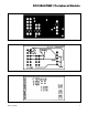
PIN SIGNAL DESCRIPTION
1
PDN
Power-down. When the pin is high, the
output buffer is enabled. When the pin
is low, the master oscillator is disabled
(power-down mode).
2 SPRD
Dither enable. When the pin is high, the
dither is enabled. When the pin is low,
the dither is disabled.
3 SCL I
2
C serial clock
4 SDA I
2
C serial data
5 GND Ground
6 VCC Power supply
7 OE
Output enable. When the pin is high,
the output buffer is enabled. When the
pin is low, the output is disabled but the
master oscillator is still on.
8 N.C. Not connected
9 SCL I
2
C serial clock
10 SDA I
2
C serial data
11 GND Ground
12 VCC Power supply
DS1086LPMB1 Peripheral Module
2Maxim Integrated
Component Supplier
Note: Indicate that you are using the DS1086LPMB1 when contacting this component supplier.
Component List
Detailed Description
I
2
C Interface
The DS1086LPMB1 peripheral module can interface to
the host in one of two ways. It can plug directly into a
Pmod-compatible port (configured for I
2
C) through con-
nector J1, or in this case, other I
2
C boards can attach to
the same I
2
C bus through connector J2.
I
2
C Interface
(Daisy-Chaining Modules)
Alternatively, the peripheral module can connect to other
I
2
C-based Pmod modules using a 4-conductor ribbon
cable connecting to the J2 connector. In this situation,
pins 1-4 and 5-8 of J2 provide two connections to the I
2
C
bus, allowing the module to be inserted into an I
2
C bus
daisy-chain.
Connector J1 provides connection of the module to the
Pmod host. The pin assignments and functions adhere
to the Pmod standard recommended by Digilent. See
Table 1.
The J2 connector allows the module to be connected
through a daisy-chain from another I
2
C module and/or
provide I
2
C and power connections to other I
2
C modules
on the same bus. See Table 2.
Table 1. Connector J1 (I
2
C Communication)