
Datasheet


3.3V Spread-Spectrum EconOscillator
Maxim Integrated 13
DS1086L
The expected output frequency is not exactly equal to the
desired frequency of 11.0592MHz. The difference is
450Hz. In terms of percentage, Equation 6 shows that the
expected error is 0.004%. The expected error assumes
typical values and does not include deviations from the
typical as specified in the electrical tables.
Example #2:
Calculate the register values needed to
generate a desired output frequency of 50MHz.
Since the desired frequency is already within the valid
master oscillator frequency range, the prescaler is set
to divide by 1, and hence, PRESCALER = 0000h
(currently ignoring the other setting).
f
MASTER OSCILLATOR
= 50.0MHz x 2
0
= 50.0MHz
Next, looking at Table 2, OS + 1 provides a range of
frequencies centered around the desired frequency. To
determine what value to write to the OFFSET register,
the RANGE register must first be read. Assuming 12h
was read in this example, 13h (OS + 1) is written to the
OFFSET register.
Finally, the DAC value is calculated as shown in
Equation 8.
The result is then converted to hex (0118h) and then
left-shifted, resulting in 4600h to be programmed into
the DAC register.
In summary, the DS1086L is programmed as follows:
PRESCALER = 0000h
OFFSET = OS + 1 or 13h (if RANGE was read as 12h)
DAC = 4600h
Since the expected output frequency is equal to the
desired frequency, the calculated error is 0%.
f
MHz kHz
OUTPUT
(. )( )
.
=
+×
=
48 6 280 5
2
50 0
0
MMHz
MHz
1
50 0.=
DAC VALUE
MHz MHz
kHz STEP SI
(. . )
=
−50 0 48 6
5
ZZE
decimal.( )= 280 00
%ERROR
ff
f
EXPECTED
DESIRED EXPECTED
DESIR
=
−
EED
EXPECTED
ERROR
MHz
%
..
×
=
−
100
11 0592 11 0
55875
11 0592
100
450
11 0592
MHz
MHz
Hz
MHz
.
.
×
=×.%100 0 004=
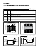
STOP
CONDITION
OR REPEATED
START
CONDITION
REPEATED IF MORE BYTES
ARE TRANSFERRED
ACK
START
CONDITION
ACK
ACKNOWLEDGEMENT
SIGNAL FROM RECEIVER
ACKNOWLEDGEMENT
SIGNAL FROM RECEIVER
SLAVE ADDRESS
MSB
SCL
SDA
R/W
DIRECTION
BIT
12 678 9 12 893–7
Figure 4. 2-Wire Data Transfer Protocol
(6)
(7)
(8)
(9)