
Datasheet


3.3V Spread-Spectrum EconOscillator
8 Maxim Integrated
DS1086L
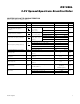
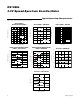
Pin Description
PIN NAME FUNCTION
1 OUT Oscillator Output. The output frequency is determined by the OFFSET, DAC, and prescaler registers.
2 SPRD Dither Enable. When the pin is high, the dither is enabled. When the pin is low, the dither is disabled.
3V
CC
Power Supply
4 GND Ground
5OE
Output Enable. When the pin is high, the output buffer is enabled. When the pin is low, the output is
disabled but the master oscillator is still on.
6 PDN
Power-Down. When the pin is high, the master oscillator is enabled. When the pin is low, the master
oscillator is disabled (power-down mode).
7 SDA
2-Wire Serial Data. This pin is for serial data transfer to and from the device. The pin is open drain and
can be wire-ORed with other open-drain or open-collector interfaces.
8 SCL
2-Wire Serial Clock. This pin is used to clock data into the device on rising edges and clock data out on
falling edges.
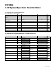
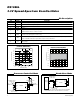
DITHERED 260kHz TO
133MHz OUTPUT
DECOUPLING CAPACITORS
(0.1μF and 0.01μF)
SPRD
OUT
V
CC
V
CC
V
CC
4.7kΩ 4.7kΩ
V
CC
2-WIRE
INTERFACE
GND
SCL
SDA
PDN
OE
DS1086L
Processor-Controlled Mode
XTL1/OSC1
μP
XTL2/OSC2
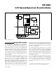
DITHERED 130kHz TO
66.6MHz OUTPUT
DECOUPLING CAPACITORS
(0.1μF and 0.01μF)
*SDA AND SCL CAN BE CONNECTED DIRECTLY HIGH IF THE DS1086L NEVER NEEDS
TO BE PROGRAMMED IN-CIRCUIT, INCLUDING DURING PRODUCTION TESTING.
SPRD
OUT
V
CC
V
CC
V
CC
GND
N.C.
SCL*
SDA*
PDN
OE
DS1086L
Stand-Alone Mode
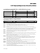
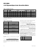
SPECTRUM COMPARISON
(12OkHz BW, SAMPLE DETECT)
DS1086L fig01
FREQUENCY (MHz)
POWER SPECTRUM (dBm)
51494745
-80
-70
-60
-50
-40
-30
-20
-10
0
-90
43 53
0.5%
NO
SPREAD
fo = 50MHz
DITHER RATE = fo/4096
2%
8%
Figure 1. Clock Spectrum Dither Comparison
MAXIMUM THERMAL VARIATION vs.
MASTER OSCILLATOR FREQUENCY
DS1086L fig02
MASTER FREQUENCY (MHz)
SUPPLY CURRENT (mA)
636036 39 42 48 51 5445 57
-4%
-3%
-2%
-1%
0
1%
2%
3%
-5%
33 66
Figure 2. Temperature Variation Over Frequency