
Datasheet


3.3V Spread-Spectrum EconOscillator
Maxim Integrated 9
DS1086L
Detailed Description
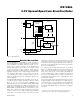
A block diagram of the DS1086L is shown in Figure 3.
The internal master oscillator generates a square wave
with a 33.3MHz to 66.6MHz frequency range. The fre-
quency of the master oscillator can be programmed
with the DAC register over a two-to-one range in 5kHz
steps. The master oscillator range is larger than the
range possible with the DAC step size, so the OFFSET
register is used to select a smaller range of frequencies
over which the DAC spans. The prescaler can then be
set to divide the master oscillator frequency by 2
x
(where x equals 0 to 8) before routing the signal to the
output (OUT) pin.
A programmable triangle-wave generator injects an off-
set element into the master oscillator to dither its output
0.5%, 1%, 2%, 4%, or 8%. The dither magnitude is con-
trolled by the JS2, JS1, and JS0 bits in the PRESCALER
word and enabled with the SPRD pin. Futhermore, the
dither rate is controlled by the JS4 and JS3 bits in the
PRESCALER word and determines the frequency of the
dither. The maximum spectral attenuation occurs when
the prescaler is set to 1 and is reduced by 2.7dB for
every factor of 2 that is used in the prescaler. This
happens because the prescaler’s divider function tends
to average the dither in creating the lower frequency.
However, the most stringent spectral emission limits are
imposed on the higher frequencies where the prescaler
is set to a low divider ratio.
The external control input, OE, gates the clock output
buffer. The PDN pin disables the master oscillator and
turns off the clock output for power-sensitive applica-
tions*. On power-up, the clock output is disabled until
power is stable and the master oscillator has generated
512 clock cycles. Both controls feature a synchronous
enable that ensures there are no output glitches when
the output is enabled.
The control registers are programmed through a 2-wire
interface and are used to determine the output frequen-
cy and settings. Once programmed into EEPROM,
since the register settings are NV, the settings only
need to be reprogrammed if it is desired to reconfigure
the device.
SDA
V
CC
SCL
2-WIRE
INTERFACE
V
CC
DAC
OFFSET
EEPROM CONTROL
REGISTERS
PRESCALER
ADDR
RANGE
SPRD
PDN
OUT
OE
DAC
TRIANGLE WAVE
GENERATOR
VOLTAGE-CONTROLLED
OSCILLATOR
PRESCALER
BY 1, 2, 4...256
GND
MASTER
OSCILLATOR
OUTPUT
DITHER SIGNAL
DITHER
CONTROL
FREQUENCY
CONTROL VOLTAGE
DS1086L
Figure 3. Block Diagram
*
The power-down command must persist for at least two out-
put frequency cycles plus 10μs for deglitching purposes.