
Datasheet


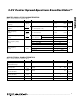
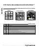


Pin Description
PIN
NAME
FUNCTION
1 OUT Oscillator Output
2
SPRD
Dither Enable. When the pin is high, the dither is enabled. When the pin is low, the dither is disabled.
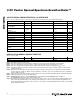
3V
CC
Power Supply
4
GND
Ground
5OE
Output Enable. When the pin is high, the output buffer is enabled. When the pin is low, the output is disabled
but the internal master oscillator is still on.
6 PDN
Power-Down. When the pin is high, the master oscillator is enabled. When the pin is low, the master oscillator
and the output buffer are disabled (power-down mode).
7 SDA I
2
C Serial Data. This pin is for serial data transfer to and from the device.
8 SCL I
2
C Serial Clock. This pin is used to clock data into and out of the device.
DS1089L
3.3V Center Spread-Spectrum EconOscillator™
6 _____________________________________________________________________
48
50
54
52
56
58
-40 10-15 35 60 85
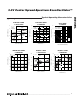
DUTY CYCLE vs. TEMPERATURE
DS 1089L toc08
TEMPERATURE (°C)
DUTY CYCLE (%)
66MHz
50MHz
130kHz
33MHz
V
CC
= 3.3V
48
50
54
52
56
58
DUTY CYCLE
vs. SUPPLY VOLTAGE
DS 1089L toc07
SUPPLY VOLTAGE (V)
DUTY CYCLE (%)
2.7 3.0 3.3 3.6
66MHz
50MHz
130kHz
33MHz
T
A
= +25°C
-90
-70
-80
-40
-50
-60
-10
-20
-30
0
44 4846 50 52 54 56
SPECTRUM COMPARISON
(120kHz BW, SAMPLE DETECT)
DS 1089L toc09
FREQUENCY (MHz)
POWER SPECTRUM (dBm)
NO SPREAD
±1%
±2%
±4%
±8%
f
MOSC
= 50MHz,
DITHER RATE = f
MOSC
/ 4096
Typical Operating Characteristics (continued)
(V
CC
= 3.3V, T
A
= +25°C, unless otherwise noted.)