
Datasheet


When dither is enabled (by selecting a dither frequency
setting greater than 0 with SPRD high), the master
oscillator frequency is dithered around the center fre-
quency by the selected percentage from the pro-
grammed f
MOSC
(see Figure 2). For example, if f
MOSC
is programmed to 40MHz (factory setting) and the
dither amount is programmed to ±1%, the frequency of
f
MOSC
will dither between 39.6MHz and 40.4MHz at a
modulation frequency determined by the selected
dither frequency. Continuing with the same example, if
J1 = 0 and J0 = 1, selecting f
MOSC
/ 2048, then the
dither frequency would be 19.531kHz.
Register Summary
The DS1089L registers are used to change the dither
amount, output frequency, and slave address. A bit
summary of the registers is shown in Table 4. Once pro-
grammed into EEPROM, the settings only need to be
reprogrammed if it is desired to reconfigure the device.
PRESCALER Register
Bits 7 to 6: Dither Frequency. The J1 and J0 bits
control the dither frequency applied to the
output. See Table 2 for divider settings. If
either of bits J1 or J0 is high and SPRD is
high, dither is enabled.
Bit 5: Output Low or Hi-Z. The LO/HIZ bit
determines the state of the output during
power-down. While the output is deacti-
vated, if the LO/HIZ bit is set to 0, the out-
put will be high impedance (high-Z). If the
LO/HIZ bit is set to 1, the output will be
driven low.
Bit 4: Reserved.
Bits 3 to 0: Prescaler Divider. The prescaler bits (bits
P3 to P0) divide the master oscillator fre-
quency by 2
x
where x can be from 0 to 8.
Any prescaler bit value entered that is
greater than 8 will decode as 8. See Table
1 for prescaler settings.
ADDR Register
Bits 7 to 6: Dither Percentage. The J3 and J2 bits
control the selected dither amplitude (%).
When both J3 and J2 are set to 0, the
default dither rate is ±1%.
Bit 5: Output Enable. The OE bit and the OE
pin state determine if the output is on
when the device is active (PDN = V
IH
). If
(OE = 0 OR OE is high) AND the PDN pin
is high, the output will be driven.
Bit 4: Reserved.
Bit 3: Write Control. The WC bit determines if
the EEPROM is to be written after register
contents have been changed. If WC = 0
(default), EEPROM is written automatically
after a write. If WC = 1, the EEPROM is
only written when the WRITE EE command
is issued. See the WRITE EE Command
section for more information.
Bits 2 to 0: Address. The A0, A1, A2 bits determine
the lower nibble of the I
2
C slave address.
DS1089L
3.3V Center Spread-Spectrum EconOscillator™
_____________________________________________________________________ 9
IF DITHER AMOUNT = 0%
(+1, 2, 4,
OR 8% OF f
MOSC
)
PROGRAMMED
f
MOSC
(-1, 2, 4,
OR 8% OF f
MOSC
)
DITHER
AMOUNT
(2, 4, 8,
OR 16%)
TIME
1
f
MOD
f
MOSC
Figure 2. Output Frequency vs. Dither Rate
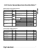
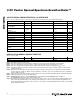
Table 4. Register Summary
REGISTER
ADDR
BIT7
BINARY
BIT0
DEFAULT
ACCESS
PRESCALER 02h
J1 J0
LO/
HIZ
X
P3 P2 P1 P0
xx00xxxxb R/W
ADDR 0Dh
J3 J2 OE
X
WC A2 A1 A0
xx100000b R/W
WRITE EE 3Fh No Data
—
—
X = “don’t care”
x = values depend on custom settings