
Datasheet


DS1210
5 of 8
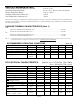
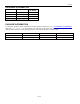
CAPACITANCE
(T
A
= +25°C)
PARAMETER
SYMBOL
MIN
TYP
MAX
UNITS
2B
NOTES
Input Capacitance
C
IN
5
pF
Output Capacitance
C
OUT
7
pF
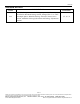
AC ELECTRICAL CHARACTERISTICS (Note 10; V
CCI
= 4.75V to 5.5V, TOL = GND)
(V
CCI
= 4.5V to 5.5V, TOL = V
CCO
)
PARAMETER
SYMBOL
MIN
TYP
MAX
UNITS
3B
NOTES
CE
Propagation Delay
t
PD
5
10
20
ns
6
CE
High to Power-Fail
t
PF
0
ns
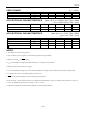
AC ELECTRICAL CHARACTERISTICS (Note 10; V
CCI
= 4.75V, TOL = GND)
(V
CCI
< 4.5, TOL = V
CCO
)
Recovery at Power Up
t
REC
2
80
125
ms
V
CC
Slew Rate Power-Down
t
F
300
µs
V
CC
Slew Rate Power-Down
t
FB
10
µs
V
CC
Slew Rate Power-Up
t
R
0
µs
CE
Pulse Width
t
CE
1.5
µs
9
NOTES:
2. All voltages are referenced to ground.
3. Only one battery input is required. Unused battery inputs must be grounded.
4. Measured with V
CCO
and
CEO
open.
5. I
CC01
is the maximum average load which the DS1210 can supply to the memories.
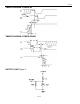
6. Measured with a load as shown in Figure 2.
7. I
CC02
is the maximum average load current which the DS1210 can supply to the memories in the battery backup mode.
8. t
CE
max must be met to ensure data integrity on power loss.
9.
CEO
can only sustain leakage current in the battery backup mode.
10. All AC and DC electrical characteristics are valid for the full temperature range. For commercial products, this range is 0
to +70°C. For industrial products (N), this range is -40°C to +85°C.
11. DS1210 is recognized by Underwriters Laboratories (UL) under file E99151.