
Datasheet


DS1220AB/AD
7 of 8
8. If
WE
is low or the
WE
low transition occurs prior to or simultaneously with the
CE
low transition,
the output buffers remain in a high-impedance state during this period.
9. Each DS1220AB and each DS1220AD has a built-in switch that disconnects the lithium source until
V
CC
is first applied by the user. The expected t
DR
is defined as accumulative time in the absence of
V
CC
starting from the time power is first applied by the user. This parameter is guaranteed by design
and is not 100% tested.
10. All AC and DC electrical characteristics are valid over the full operating temperature range. For
commercial products, this range is 0°C to 70°C. For industrial products (IND), this range is -40°C to
+85°C.
11. In a power down condition the voltage on any pin may not exceed the voltage on V
CC
.
12. t
WR1
, t
DH1
are measured from
WE
going high.
13. t
WR2
, t
DH2
are measured from
CE
going high.
14. DS1220 modules are recognized by Underwriters Laboratories (UL) under file E99151.
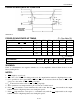
DC TEST CONDITIONS
Outputs Open
Cycle = 200ns for Operating Current
All Voltages Are Referenced to Ground
AC TEST CONDITIONS
Output Load: 100 pF + 1TTL Gate
Input Pulse Levels: 0 - 3.0V
Timing Measurement Reference Levels
Input: 1.5V
Output: 1.5V
Input Pulse Rise and Fall Times: 5ns
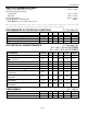
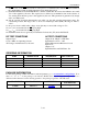
ORDERING INFORMATION
PART TEMP RANGE
SUPPLY
TOLERANCE
PIN-PACKAGE
DS1220AB-100+
0°C to +70°C
5V ± 5%
24 720 EDIP
DS1220AB-100IND+
-40°C to +85°C
5V
±
5%
24 720 EDIP
DS1220AD-100+
0°C to +70°C
5V
±
10%
24 720 EDIP
DS1220AD-100IND+
-40°C to +85°C
5V ± 10%
24 720 EDIP
+Denotes a lead(Pb)-free/RoHS-compliant package.
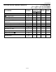
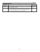
PACKAGE INFORMATION
For the latest package outline information and land patterns, go to www.maxim-ic.com/packages. Note
that a “+”, “#”, or “-” in the package code indicates RoHS status only. Package drawings may show a
different suffix character, but the drawing pertains to the package regardless of RoHS status.
PACKAGE TYPE PACKAGE CODE OUTLINE NO.
LAND
PATTERN NO.
24 EDIP MDT24+1
21-0245