
Datasheet


DS1306
6 of 22
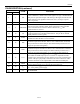
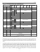
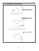
Figure 2. RTC REGISTERS AND ADDRESS MAP
HEX ADDRESS
READ
WRITE
Bit7 Bit6 Bit5 Bit4 Bit3 Bit2 Bit1 Bit0 RANGE
00h 80h 0 10 SEC SEC 00–59
01h 81h 0 10 MIN MIN 00–59
P
12
A
01–12 + P/A
02h 82h 0
24 10
10-HR HOURS
00–23
03h 83h 0 0 0 0 0 DAY 01–07
04h 84h 0 0 10-DATE DATE 1–31
05h 85h 0 0 10-MONTH MONTH 01–12
06h 86h 10-YEAR YEAR 00–99
07h 87h M 10-SEC ALARM 0 SEC ALARM 0 00–59
08h 88h M 10-MIN ALARM 0 MIN ALARM 0 00–59
P
12
A
01–12 + P/A
09h 89h M
24 10
10-HR HOUR ALARM 0
00–23
0Ah 8Ah M 0 0 0 0 DAY ALARM 0 01–07
0Bh 8Bh M 10 SEC ALARM 1 SEC ALARM 1 00–59
0Ch 8Ch M 10 MIN ALARM 1 MIN ALARM 1 00–59
P
12
A
01–12 + P/A
0Dh 8Dh M
24 10
10-HR HOUR ALARM 1
00–23
0Eh 8Eh M 0 0 0 0 DAY ALARM 1 01–07
—
0Fh 8Fh CONTROL REGISTER —
10h 90h STATUS REGISTER —
11h 91h TRICKLE CHARGER REGISTER —
12h–1Fh
92h–
9Fh
RESERVED —
20h–7Fh
A0h–
FFh
96-BYTES USER RAM —
Note: Range for alarm registers does not include mask’m’ bits.
The DS1306 can be run in either 12-hour or 24-hour mode. Bit 6 of the hours register is defined as the
12- or 24-hour mode select bit. When high, the 12-hour mode is selected. In the 12-hour mode, bit 5 is the
AM/PM bit with logic-high being PM. In the 24-hour mode, bit 5 is the second 10-hour bit (20 to 23
hours).
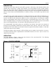
The DS1306 contains two time-of-day alarms. Time-of-day alarm 0 can be set by writing to registers 87h
to 8Ah. Time-of-day Alarm 1 can be set by writing to registers 8Bh to 8Eh. Bit 7 of each of the time-of-
day alarm registers are mask bits (Table 2). When all of the mask bits are logic 0, a time-of-day alarm
only occurs once per week when the values stored in timekeeping registers 00h to 03h match the values
stored in the time-of-day alarm registers. An alarm is generated every day when bit 7 of the day alarm
register is set to a logic 1. An alarm is generated every hour when bit 7 of the day and hour alarm