
Datasheet

DS1307 64 x 8, Serial, I
2
C Real-Time Clock
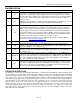
ABSOLUTE MAXIMUM RATINGS
Voltage Range on Any Pin Relative to Ground .................................................................................... -0.5V to +7.0V
Operating Temperature Range (Noncondensing)
Commercial ................................................................................................................................ 0°C to +70°C
Industrial .................................................................................................................................. -40°C to +85°C
Storage Temperature Range ............................................................................................................. -55°C to +125°C
Soldering Temperature (DIP, leads) ........................................................................................ +260°C for 10 seconds
Soldering Temperature (surface mount)…..……………………….Refer to the JPC/JEDEC J-STD-020 Specification.
Stresses beyond those listed under “Absolute Maximum Ratings” may cause permanent damage to the device. These are stress ratings only,
and functional operation of the device at these or any other conditions beyond those indicated in the operational sections of the specifications is
not implied. Exposure to the absolute maximum rating conditions for extended periods may affect device reliability.
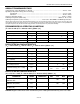
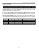
RECOMMENDED DC OPERATING CONDITIONS
(T
A
= 0°C to +70°C, T
A
= -40°C to +85°C.) (Notes 1, 2)
PARAMETER SYMBOL CONDITIONS MIN TYP MAX UNITS
Supply Voltage V
CC
4.5 5.0 5.5 V
Logic 1 Input V
IH
2.2 V
CC
+ 0.3 V
Logic 0 Input V
IL
-0.3 +0.8 V
V
BAT
Battery Voltage V
BAT
2.0 3 3.5 V
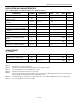
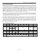
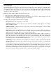
DC ELECTRICAL CHARACTERISTICS
(V
CC
= 4.5V to 5.5V; T
A
= 0°C to +70°C, T
A
= -40°C to +85°C.) (Notes 1, 2)
PARAMETER SYMBOL CONDITIONS MIN TYP MAX UNITS
Input Leakage (SCL) I
LI
-1 1
µA
I/O Leakage (SDA, SQW/OUT) I
LO
-1 1
µA
Logic 0 Output (I
OL
= 5mA) V
OL
0.4 V
Active Supply Current
(f
SCL
= 100kHz)
I
CCA
1.5 mA
Standby Current I
CCS
(Note 3) 200
µA
V
BAT
Leakage Current I
BATLKG
5 50 nA
Power-Fail Voltage (V
BAT
= 3.0V) V
PF
1.
216 x
V
BAT
1.25 x
V
BAT
1.284 x
V
BAT
V
DC ELECTRICAL CHARACTERISTICS
(V
CC
= 0V, V
BAT
= 3.0V; T
A
= 0°C to +70°C, T
A
= -40°C to +85°C.) (Notes 1, 2)
PARAMETER SYMBOL CONDITIONS MIN TYP MAX UNITS
V
BAT
Current (OSC ON);
SQW/OUT OFF
I
BAT1
300 500 nA
V
BAT
Current (OSC ON);
SQW/OUT ON (32kHz)
I
BAT2
480 800 nA
V
BAT
Data-Retention Current
(Oscillator Off)
I
BATDR
10 100 nA
WARNING: Negative undershoots below -0.3V while the part is in battery-backed mode may cause loss of data.
2 of
14