
Datasheet


DS1314
2 of 12
In addition to battery-backup support, the DS1314 performs the important function of monitoring the
remaining capacity of the lithium battery and providing a warning before the battery reaches end-of-life.
Because the open-circuit voltage of a lithium backup battery remains relatively constant over the majority
of its life, accurate battery monitoring requires loaded-battery voltage measurement. The DS1314
performs such measurement by periodically comparing the voltage of the battery as it supports an internal
resistive load with a carefully selected reference voltage. If the battery voltage falls below the reference
voltage under such conditions, the battery will soon reach end-of-life. As a result, the Battery Warning
pin is activated to signal the need for battery replacement.
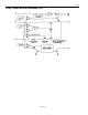
MEMORY BACKUP
The DS1314 performs all the circuit functions required to provide battery-backup for an SRAM. First, the
device provides a switch to direct power from the battery or the system power supply (V
CCI
). Whenever
V
CCI
is less than the switch point V
SW
and V
CCI
is less than the battery voltage V
BAT
, the battery is
switched in to provide backup power to the SRAM. This switch has voltage drop of less than 0.2 volts.
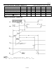
Second, the DS1314 handles power failure detection and SRAM write protection. V
CCI
is constantly
monitored, and when the supply goes out of tolerance, a precision comparator detects power failure and
inhibits chip enable output (
CEO
) in order to write-protect the SRAM. This is accomplished by holding
CEO
to within 0.2 volts of V
CCO
when V
CCI
is out of tolerance. If
CEI
is (active) low at the time that
power failure is detected, the
CEO
signal is kept low until
CEI
is brought high again. Once
CEI
is
brought high,
CEO
is taken high and held high until after V
CCI
has returned to its nominal voltage level. If
CEI
is not brought high by 1.5 µs after power failure is detected,
CEO
is forced high at that time. This
specific scheme for delaying write protection for up to 1.5 µs guarantees that any memory access in
progress when power failure occurs will complete properly. Power failure detection occurs at 3.0V
nominal (3.3V supply) when the TOL pin is wired to GND or at 2.7V nominal (3.0V supply) when TOL
is connected to V
CCO
.
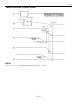
BATTERY VOLTAGE MONITORING
The DS1314 automatically performs periodic battery voltage monitoring at a factory-programmed time
interval of 24 hours. Such monitoring begins within t
REC
after V
CCI
rises above V
CCTP
, and is suspended
when power failure occurs.
After each 24-hour period (t
BTCN
) has elapsed, the DS1314 connects V
BAT
to an internal 1.2 MΩ test
resistor (R
INT
) for one second (t
BTPW
). During this one second, if V
BAT
falls below the factory-
programmed battery voltage trip point (V
BTP
), the battery warning output
BW
is asserted. While
BW
is
active battery testing will be performed with period t
BTCW
to detect battery removal and replacement.
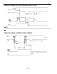
Once asserted,
BW
remains active until the battery is physically removed and replaced by a fresh cell.
The battery is still re-tested after each V
CC
power-up, however, even if
BW
was active on power-down. If
the battery is found to be higher than V
BTP
during such testing,
BW
is deasserted and regular 24-hour
testing resumes.
BW
has an open-drain output driver.
Battery replacement following
BW
activation is normally done with V
CCI
nominal so that SRAM data is
not lost. During battery replacement, the minimum time duration between old battery detachment and
new battery attachment (t
BDBA
) must be met or
BW
will not deactivate following attachment of the new