
Datasheet
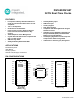


DS1685/DS1687 3V/5V Real-Time Clocks
7 of 34
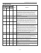
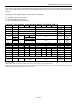
Table 1. Crystal Specifications*
8BPARAMETER 9BSYMBOL MIN TYP MAX UNITS
Nominal Frequency
f
O
32.768
kHz
Series Resistance
ESR
50
kΩ
Load Capacitance
C
L
6, 12.5
pF
*The crystal, traces, and crystal input pins should be isolated from RF generating signals. Refer to Application Note 58: Crystal Considerations
for Dallas Real-Time Clocks for additional specifications.
CLOCK ACCURACY
The accuracy of the clock is dependent on the accuracy of the crystal and the accuracy of the match between the
capacitive load of the oscillator circuit and the capacitive load for which the crystal was trimmed. Additional error is
added by crystal frequency drift caused by temperature shifts. External circuit noise coupled into the oscillator
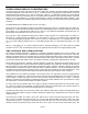
circuit can result in the clock running fast. Figure 3 shows a typical PC board layout for isolation of the crystal and
oscillator from noise. Refer to Application Note 58: Crystal Considerations with Dallas Real-Time Clocks for
detailed information.
The DS1685 can also be driven by an external 32.768 kHz oscillator. In this configuration, the X1 pin is connected
to the external oscillator signal and the X2 pin is floated. Refer to Application Note 58: Crystal Considerations with
Dallas Real-Time Clocks for detailed information about crystal selection and crystal layout.
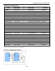
Figure 2. Oscillator Circuit Showing Internal Bias Network
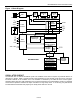
Figure 3. Typical Crystal Layout
Countdown
Chain
RTC
X1
X2
Crystal
C
L
1 C
L
2
RTC
Registers
Local ground plane (Layer 2)
crystal
X1
X2
GND
NOTE: AVOID ROUTING SIGNAL LINES IN
THE CROSSHATCHED AREA (UPPER
LEFT QUADRANT) OF THE PACKAGE
UNLESS THERE IS A GROUND PLANE
BETWEEN THE SIGNAL LINE AND THE
DEVICE PACKAGE.