
Datasheet

DS1685/DS1687 3V/5V Real-Time Clocks
9 of 34
“don’t care” codes in all three time alarm bytes create an interrupt every second. The three time-alarm bytes can be
used with the date alarm as described in the Wake-Up/Kickstart section. The century counter is discussed later in
this text.
All registers can be directly written or read except for the following:
1) Registers C and D are read-only.
2) Bit 7 of Register A is read-only.
3) Bit 7 of the seconds byte is read-only.
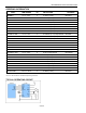
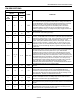
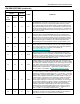
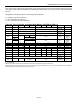
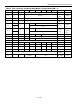
Table 2A. Time, Calendar, and Alarm Data Modes—BCD Mode (DM = 0)
ADDRESS BIT 7 BIT 6 BIT 5 BIT 4 BIT 3 BIT 2 BIT 1 BIT 0 FUNCTION RANGE
00H
0
10 Seconds
Seconds
Seconds
00-59
01H 0 10 Seconds Seconds
Seconds
Alarm
00-59
02H
0
10 Minutes
Minutes
Minutes
00-59
03H 0 10 Minutes Minutes
Minutes
Alarm
00-59
04H
AM/PM
0
0 10 Hour
Hours Hours
1-12
+AM/PM
00-23
0 10 Hour
05H
AM/PM
0
0
10 Hour
Hours
Hours
Alarm
1-12
+AM/PM
00-23
0 10 Hr
06H
0
0
0
0
0
Day
Day
01-07
07H
0
0
10 Date
Date
Date
01-31
08H
0
0
0
10 Month
Month
Month
01-12
09H
10 Year
Year
Year
00-99
0AH UIP DV2 DV1 DV0 RS3 RS2 RS1 RS0 Control
0BH SET PIE AIE UIE SQWE DM 24/12 DSE Control
0CH IRQF PF AF UF 0 0 0 0 Control
0DH VRT 0 0 0 0 0 0 0 Control
48H Century
Bank 1
Century
00-99
49H 10 Date Date
Bank 1
Date Alarm
01-31
X = Read/Write Bit.
Note 1: Unless otherwise specified, the state of the registers is not defined when power is first applied.
Note 2: Except for the seconds register, 0 bits in the time and date registers can be written to a 1, but may be modified when the clock updates.
0 bits should always be written to 0 except for alarm mask bits.