
Datasheet
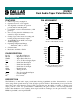


DS1801
2 of 10
OPERATION
The DS1801 provides two 65-position potentiometers per package, each having a logarithmic resistive
characteristic as shown in Table 1. The DS1801 is controlled by a 3-wire serial interface. The 3-wire
serial interface is designed for CPU-controlled applications and allows the potentiometer’s exact wiper
position to be read or written. The DS1801 design supports daisy-chaining for multi-device
environments.
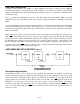
Figure 1 presents a block diagram of the DS1801. As shown, the inputs from the 3-wire serial interface
drive a command/control unit. The command/control unit interprets these inputs for control of the two
potentiometers.
On power-up, the serial port is stable and active within 10 microseconds. The wiper position on power-up
will be at position 63, the low end of the potentiometer. Position 64 is the mute level.
RESISTANCE CHARACTERISTICS Table 1
POSITION OUTPUT LEVEL (dB)
00
1-1
2-2
3-3
4-4
5-5
63 -63
64(mute) <-90
DS1801 BLOCK DIAGRAM Figure 1