
Datasheet


DS1801
9 of 10
AC ELECTRICAL CHARACTERISTICS (-40°C to +85°C; V
CC
=2.7V to 5.5V)
PARAMETER SYMBOL MIN TYP MAX UNITS NOTES
CLK Frequency f
CLK
DC 10 MHz 7
Width of CLK Pulse t
CH
50 ns 7
Data Setup Time t
DC
30 ns 7
Data Hold Time t
CDH
10 ns 7
Propagation Delay Time
Low to High Level
Clock to Output
t
PLH
50 ns 7
Propagation Delay Time
Low to High Level
t
PLH
50 ns 7
RST High to Clock Input High
t
CC
50 ns 7
RST Low to Clock Input High
t
HLT
50 ns 7
CLK Rise Time t
CR
60 ns 7
RST Inactive
t
RLT
200 ns 7
NOTES:
1. All voltages are referenced to ground.
2. Valid for V
CC
= 2V only.
3. Capacitance values apply at 25°C.
4. Inter-channel matching is used to determine the relative voltage difference in dB between the same
tap position on each potentiometer. The DS1801 is specified for ±0.5 dB inter-channel matching.
5. Tap-to-tap tolerance is used to determine the change in voltage between successive tap positions. The
DS1801 is specified for ±0.25 dB tap-to-tap tolerance.
6. Typical values are for T
A
=25°C and nominal supply voltage.
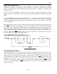
7. See Figure 3.
8. Absolute tolerance is used to determine measured wiper voltage vs. expected wiper voltage as
determined by wiper position. The DS1801 is bounded by a ±1 dB absolute tolerance.
9. Maximum current specifications are based on clock rate and active zero-crossing detection. See
Figure 5 for clock rate vs. current specification.
10. See Figure 7.
11. Standby current levels apply when all inputs are driven to appropriate supply levels.
12. These parameters are characterized and not 100% tested.
13. Valid at 25° C only.