
Datasheet


DS1802
10 of 17
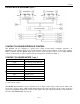
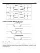
CASCADE OPERATION
A feature of the DS1802 is the ability to control multiple devices from a single processor. Multiple
DS1802s can be linked or daisy-chained as shown in Figure 7. As a bit is entered in to the I/O shift
registeroftheDS1802 it will appear at the C
OUT
out put after a maximum delay of 50 nanoseconds.
The C
OUT
output of the DS1802 can be used to drive the D input of another DS1802. When connecting
multiple devices, the total number of bits sent is always 16 times the number of DS1802s in the daisy
chain.
An optional feedback resistor can be placed between the C
OUT
terminal of the last device and the D input
of the first DS1802, thus allowing the controlling processor to circularly clock data through the daisy
chain. The value of the feedback or isolation resistor should be in the range from 2 kΩ to 10 kΩ.
When reading data via the C
OUT
pin and isolation resistor, the D line is left floating by the reading device.
When RST is driven high, bit 0 is present on the C
OUT
pin, which is fed back to the input D pin through
the isolation resistor. When the CLK input transitions low to high, bit 0 is loaded into the first position of
the I/O shift register and bit 1 becomes present on C
OUT
and D of the next device. After 16 bits (or 16
times the number of DS1802s in the daisy chain), the data has shifted completely around and back to its
original position. When RSTtransitions to the low state to end data transfer, the value (the same as before
the read occurred) is loaded into the wiper-0 and wiper-1.
CASCADING MULTIPLE DEVICES Figure 7
Zero-Crossing Detection
The DS1802 provides a zero-crossing detection capability when using the 3-Wire Serial interface. Zero-
crossing detection provides a means for minimizing any audible noise that may result from sizable
discrete wiper transitions when using the part in audio applications. The zero-crossing detect feature
allows independent wiper changes only when the two terminals of the potentiometer have equal potentials
and within a 50 ms time window from the fall of the RSTsignal. If at 50 ms the DS1802 has not detected
a zero-crossing, the wiper position of the potentiometer(s) will change regardless of the state of the input
signal. Zero-crossing detection is activated when the ZCENinput level is in a low state. When high, the
ZCENinput deactivates both the 50 ms time requirement and zero-crossing detection.
Zero-crossing detection is also available when using the part in pushbutton operation. When a pushbutton
is activated, the part will change wiper position during the first detected zero-crossing or at the end of a
50 ms time window.
When operating in pushbutton operation with a continuous input pulse, the wiper position will change
once during the initial 1-second time period. This change is dictated by a detected zero-crossing or 50 ms