
Datasheet


DS1803
7 of 11
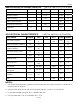
ANALOG RESISTOR CHARACTERISTICS (-40°C to +85°C;V
CC
=2.7V to 5.5V)
PARAMETER SYMBOL MIN TYP MAX UNITS NOTES
End-to-End Resistor Tolerance -20 +20 % 17
Absolute Linearity
±0.75
LSB
13
Relative Linearity
±0.3
LSB
14
-3 dB Cutoff Frequency f
CUTOFF
Hz 11
Temperature Coefficient 750
ppm/°C
Capacitance C
I
5
pF
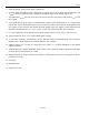
AC ELECTRICAL CHARACTERISTICS (-40°C to +85°C;V
CC
=2.7V to 5.5V)
PARAMETER SYMBOL MIN TYP MAX UNITS NOTES
SCL Clock Frequency f
SCL
0
0
400
100
kHz
15
16
Bus Free Time Between
STOP and START Condition
t
BUF
1.3
4.7
μs
15
16
Hold Time (Repeated)
START Condition
t
HD:STA
0.6
4.0
μs 5
Low Period of SCL Clock t
LOW
1.3
4.7
μs
High Period of SCL Clock t
HIGH
0.6
4.0
μs
Data Hold Time t
HD :DAT
0
0
0.9 μs 6,7
Data Setup Time t
SU :DAT
100
250
ns 8
Rise Time of both SDA and
SCL Signals
t
R
20+1C
B
300
1000
ns 9
Fall Time of both SDA and
SCL Signals
t
F
20+1C
B
300
300
ns 9
Setup Time for STOP
Condition
t
SU:STO
0.6
4.0
µs
Capacitive Load for each Bus
Line
C
B
400 pF 9
NOTES:
1. All voltages are referenced to ground. Currents flowing into device pins are positive. Currents out of
the device pins are negative.
2. I/O pins of fast mode devices will not obstruct SDA and SCL even if V
CC
is switched off.
3. I
CC
specified with SDA pin open, SCL = 400 kHz clock rate.
4. I
STBY
specified with V
CC
at 5.0V and SDA, SCL = 5.0V.