
Datasheet


DS1805
Addressable Digital Potentiometer
6 _____________________________________________________________________
Detailed Description
The DS1805 addressable digital potentiometer contains a
single 256-position digitally controlled potentiometer.
Device control is achieved through a 2-wire serial inter-
face. Device addressing is provided through three
address inputs that allow up to eight devices on a single
2-wire bus. The exact wiper position of the potentiometer
can be written or read. The DS1805 is available in 16-pin
SO and 14-pin TSSOP packages. The device is available
in three standard resistance values: 10kΩ, 50kΩ, and
100kΩ. The DS1805 specified over the industrial temper-
ature range. The DS1805 is provides a low-cost alterna-
tive for designs based on the DS1803, but require only a
single potentiometer.
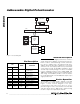
Device Operation
The DS1805 is an addressable, digitally controlled
device that has a single 256-position potentiometer.
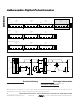
Figure 1 shows a block diagram of the part.
Communication and control of the device is accom-
plished through a 2-wire serial interface that has SDA
and SDL signals. Device addressing is attained using
the device chip-select inputs A0, A1, and A2.
W1
SCL
SDA
A0
A1
A2
2-WIRE SERIAL
INTERFACE
REG-0 (8-BIT REGISTER)
SRAM
WIPER-1 (8-BIT REGISTER)
COMMAND/
CONTROL
UNIT
DEVICE ADDRESS
SELECTION
L1
256-TO-1 MULTIPLEXER
POTENTIOMETER-1
H1
Figure 1. Functional Diagram
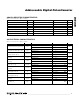
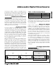
PIN
TSSOP
SO
NAME FUNCTION
11 H1
High End of
Potentiometer
23 L1
Low End of
Potentiometer
34 W1
Wiper Terminal of
Potentiometer
6, 5, 4
7, 6, 5
A0, A1, A2
Address Select Inputs
7 8 GND Ground
8 9 SCL Serial Clock Input
9 10 SDA Serial Data I/O
10–13
2, 11–15
N.C. No Connection
14 16 V
CC
3V/5V Power-Supply
Input
Pin Description