
Datasheet


DS1806
3 of 8 102199
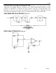
Wiper placement for each potentiometer is such that position-63 corresponds to the H
X
terminal of the de-
vice while position-0 corresponds to the ground terminal. For example, to set a potentiometer’s wiper
position to 15 (decimal), the binary value shifted into the wiper register should be 00001111. This will
place the wiper tap at the 15
th
step above the low-end terminal, L
X
.
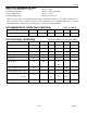
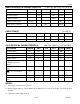
All communication transactions should provide the total 48 bits of information when writing or reading
from the part. This is especially true for applications using all six potentiometers. If a complete set of 48
bits is not transmitted to the part, undesired wiper position settings may occur.
DS1806 BLOCK DIAGRAM Figure 1
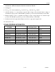
WIPER REGISTER CONFIGURATION Figure 2
48-BIT I/O SHIFT REGISTER Figure 3