
Datasheet
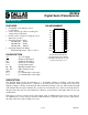


DS1806
8 of 8 102199
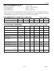
4. -3 dB cutoff frequency characteristics for the DS1806 depend on potentiometer total resistance:
DS1806-010; 1 MHz; DS1806-050; 200 kHz, DS1806-100; 100 kHz.
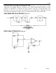
5. See Figure 4.
6. For V
CC
= 5V ± 10% maximum V
IL
= +0.8V. For V
CC
= 3.0 ± 10% V
IL
= +0.6V.
7. Absolute linearity is to used measure expected wiper voltage versus measured wiper voltage as
determined by wiper position. The DS1806 is specified to provide an absolute linearity of +0.5 LSB.
8. Relative linearity is used to determine the change in wiper voltage between two adjacent wiper
positions. The DS1806 is specified to provide a relative linearity of +0.25 LSB.
9. Standby current levels apply when all inputs are driven to appropriate supply levels.
10. Valid at 25°C only.
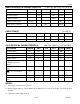
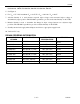
DS1806 ORDERING INFORMATION
ORDERING
NUMBER
PACKAGE
OPERATING
TEMPERATURE
VERSION
DS1806-010 20L DIP -40°C TO +85°C
10 kΩ
DS1806-050 20L DIP -40°C TO +85°C 50 kΩ
DS1806-100 20L DIP -40°C TO +85°C 100 kΩ
DS1806E-010 20L TSSOP (173-mil) -40°C TO +85°C
10 kΩ
DS1806E-050 20L TSSOP (173-mil) -40°C TO +85°C 50 kΩ
DS1806E-100 20L TSSOP (173-mil) -40°C TO +85°C 100 kΩ
DS1806S-010 20L SOIC (300-mil) -40°C TO +85°C
10 kΩ
DS1806S-050 20L SOIC (300-mil) -40°C TO +85°C 50 kΩ
DS1806S-100 20L SOIC (300-mil) -40°C TO +85°C 100 kΩ