
Datasheet


DS1904
12 of 13
NOTES:
1. A
ll voltages are referenced to ground.
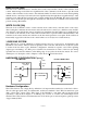
2. V
PUP
= external pull-up voltage; see Figure 6.
3. Under certain low voltage conditions V
IL1MAX
may have to be reduced to as much as 0.5V to always
guarantee a presence pulse.
4. Input load is to ground.
5. Guaranteed by design; not production tested.
6. The master must read while the data is valid.
7. Read data setup time refers to the time the host must pull the 1-Wire bus low to read a bit. Data is
guaranteed to be valid within 1 µs of this falling edge.
8. The reset low time (t
RSTL
) should be restricted to a maximum of 960 µs, to allow interrupt signaling,
o
therwise, it could mask or conceal interrupt pulses.
9. This specification applies if the 1-Wire is idle (high or low). Communication on the 1-Wire may
adversely affect the accuracy of the device. For highest accuracy, connect the DS1904 to a separate
1-Wire port and limit the access to the minimum acceptable by the application.
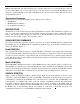
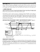
PRODUCT LIFETIME VS. TEMPERATURE
0.00
2
.00
4.00
6.00
8.00
10.00
12.00
14.00
16.00
18.00
20.00
22.00
-40 -30 -20 -10 0 10 20 30 40 50 60 70 80
Temperature (°C)
Expected Service Life (years)
PACKAGE INFORMATION
For the latest package outline information and land patterns (footprints), go to www.maximintegrated.com/packages. Note
that a “+”, “#”, or “-” in the package code indicates RoHS status only. Package drawings may show a different suffix
character, but the drawing pertains to the package regardless of RoHS status.
PACKAGE TYPE PACKAGE CODE OUTLINE NO. LAND PATTERN NO.
F5 iButton IB#5CB
21-0266
—