
Datasheet


DS1904
2 of 13
ground return. The DS1904 contains a unique 64-bit factory-lasered ROM and a real-time clock/calendar
i
mplemented as a binary counter. The durable MicroCan package is highly resistant to environmental
hazards such as dirt, moisture, and shock. Accessories permit the DS1904 to be mounted on almost any
surface including printed circuit boards and plastic key fobs. The DS1904 adds functions such as
calendar, time and date stamp, stopwatch, hour meter, interval timer, and logbook to any type of
electronic device or embedded application that uses a microcontroller.
OVERVIEW
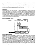
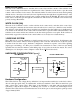
The DS1904 has two main data components: 1) 64-bit lasered ROM, and 2) real-time clock counter
(
Figure 1). The real-time clock utilizes an on-chip oscillator that is connected to a 32.768 kHz crystal.
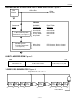
The hierarchical structure of the 1-Wire protocol is shown in Figure 2. The bus master must first provide
one of four ROM function commands: 1) Read ROM, 2) Match ROM, 3) Search ROM, 4) Skip ROM.
The protocol for these ROM functions is described in Figure 7. After a ROM function command is
successfully executed, the real-time clock functions become accessible and the master may then provide
one of the real-time clock function commands. The protocol for these commands is described in Figure 5.
All data is read and written least significant bit first.
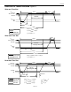
BLOCK DIAGRAM Figure 1
1 Hz
DIVIDER
DATA
ROM
CONTROL
FUNCTION
64-BIT
ROM
LASERED
CLOCK
FUNCTION
CONTROL
OSCILLATOR
CONTROL
READ/WRITE BUFFER
RTC COUNTER (32-BIT)
32.768 kHz
OSCILLATOR
LID
CONTACT
LITHIUM
3V
64-BIT LASERED ROM
Each DS1904 contains a unique ROM code that is 64 bits long. The first eight bits are a 1-Wire family
code. The next 48 bits are a unique serial number. The last eight bits are a CRC of the first 56 bits (see
Figure 3). The 1-Wire CRC is generated using a polynomial generator consisting of a shift register and
XOR gates as shown in Figure 4. The polynomial is X
8
+ X
5
+ X
4
+ 1. Additional information about the
Maxim 1-Wire Cyclic Redundancy Check is available in Application Note 937: Book of iButton®
Standards. The shift register bits are initialized to zero. Then starting with the least significant bit of the
family code, one bit at a time is shifted in. After the 8th bit of the family code has been entered, then the
serial number is entered. After the 48th bit of the serial number has been entered, the shift register
contains the CRC value. Shifting in the eight bits of CRC should return the shift register to all zeros. The
64-bit ROM and ROM Function Control section allow the DS1904 to operate as a 1-Wire device and
follow the 1-Wire protocol detailed in the 1-Wire Bus System section.