
Datasheet


DS1904
6 of 13
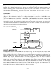
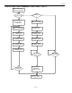
READ CLOCK [66h]
The read clock command is used to read the device control byte and the contents of the real-time clock
c
ounter. After having received the most significant bit of the command code the device copies the actual
contents of the real-time clock counter to the read/write buffer. Now the bus master reads data beginning
with the device control byte followed by the least significant byte through the most significant byte of the
real-time clock. After this the bus master may continue reading from the DS1904. The data received will
be the same as in the first pass through the command flow. The read clock command can be ended at any
point by issuing a Reset Pulse.
WRITE CLOCK [99h]
The write clock command is used to set the real-time clock counter and to write the device control byte.
A
fter issuing the command, the bus master writes first the device control byte, which becomes immedi-
ately effective. After this the bus master sends the least significant byte through the most significant byte
to be written to the real-time clock counter. The new time data is copied from the read/write buffer to the
real-time clock counter and becomes effective as the bus master generates a reset pulse. If the oscillator is
intentionally stopped, the real-time clock counter behaves as a four-byte non-volatile memory.
1-WIRE BUS SYSTEM
The 1-Wire bus is a system, which has a single bus master and one or more slaves. In all instances the
DS1904 is a slave device. The bus master is typically a microcontroller. The discussion of this bus system
is broken down into three topics: hardware configuration, transaction sequence, and 1-Wire signaling
(signal types and timing). A 1-Wire protocol defines bus transactions in terms of the bus state during
specified time slots that are initiated on the falling edge of sync pulses from the bus master. For a more
detailed protocol description, refer to Chapter 4 of the Book of iButton® Standards.
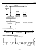
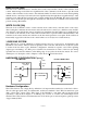
HARDWARE CONFIGURATION Figure 6
RX
TX
Open Drain
Port Pin
5 µA
Typ.
DS1904 1-WIRE PORT
RX = RECEIVE
TX = TRANSMIT
BUS MASTER
V
PUP
DATA
RX
TX
MOSFET
100 Ω
5 k Ω
Typ.
Hardware Configuration
The 1-Wire bus has only a single line by definition; it is important that each device on the bus be able to
drive it at the appropriate time. To facilitate this, each device attached to the 1-Wire bus must have open
drain or three-state outputs. The 1-Wire input of the DS1904 is open drain with an internal circuit
equivalent to that shown in Figure 6. A multidrop bus consists of a 1-Wire bus with multiple slaves
attached. The 1-Wire bus has a maximum data rate of 16.3k bits per second and requires a pull-up resistor
of approximately 5kΩ.