
Datasheet


DS2762 High-Precision Li+ Battery Monitor With Alerts
6 of 25
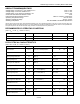
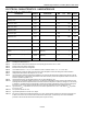
PIN DESCRIPTION
PIN
TSSOP
FLIP
CHIP
SYMBOL FUNCTION
1 C1
CC
Charge Protection Control Output. Controls an external P-channel high-side charge
protection FET.
2 B1 PLS
Battery Pack Positive Terminal Input. The DS2762 monitors the pack plus terminal
through PLS to detect overcurrent and overload conditions, as well as the presence of a
charge source. Additionally, a charge path to recover a deeply depleted cell is provided
from PLS to V
DD
. In sleep mode (with SWEN = 0), any capacitance or voltage source
connected to PLS is discharged internally to V
SS
through 200µA (nominal) to assure
reliable detection of a valid charge source. For details of other internal connections to
PLS and associated conditions see the Li+ Protection Circuitry section.
3 B2
DC
Discharge Protection Control Output. Controls an external P-channel high-side
discharge protection FET.
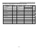
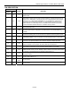
4, 5, 6 A3 SNS
Sense Resistor Connection. Connect to the negative terminal of the battery pack. In
the internal sense resistor configuration, the sense resistor is connected between V
SS
and SNS.
7 B4 DQ
Data Input/Out. 1-Wire data line. Open-drain output driver. Connect this pin to the DATA
terminal of the battery pack. Pin has an internal 1mA pulldown for sensing disconnection.
8 C4 IS2
Current-Sense Input. This pin is internally connected to SNS through a 4.7kW resistor.
9 D4 IS1
Current-Sense Input. This pin is internally connected to V
SS
through a 4.7kW resistor.
Connect a 0.1mF capacitor between IS1 and IS2 to complete a lowpass input filter.
10 E4
PS
Power Switch Sense Input. The device wakes up from sleep mode when it senses the
closure of a switch to V
SS
on this pin. Pin has an internal 1mA pullup to V
DD
.
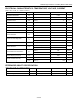
11, 12, 13 F3
V
SS
Device Ground. Connect directly to the negative terminal of the Li+ cell. For the external
sense resistor configuration, connect the sense resistor between V
SS
and SNS.
14 E2
PIO
Programmable I/O Pin. Can be configured to be used to control and monitor user-
defined external circuitry or as an interrupt output to alert the host when preset current
accumulator or temperature limits are exceeded. Open drain to V
SS
.
15 E1 V
DD
Power-Supply Input. Connect to the positive terminal of the Li+ cell through a
decoupling network.
16 D1 V
IN
Voltage Sense Input. The voltage of the Li+ cell is monitored through this input pin. This
pin has a weak pullup to V
DD
.
— C2
SNS
Probe
Do not connect.
— D2
V
SS
Probe
Do not connect.