
Datasheet


DESIGNATION QTY DESCRIPTION
BAT1 1
Battery holder
Memory Protection Devices
BH401
C1 1
1FF Q10%, 10V X7R ceramic
capacitor (0603)
TDK C1608X7R1A105K
C2 1
0.1FF Q10%, 10V X74 ceramic
capacitor (0603)
Murata GRM188R71C104KA01D
DESIGNATION QTY DESCRIPTION
J1 1 6-pin right-angle male header
J2 1
8-pin (2 x 4) straight male
header
R1–R4 4
150I Q5% resistors (0603)
R5–R8 4
4.7kI Q5% resistors (0603)
U1 1
Q5ppm, I
2
C real-time clock
(8 SO)
Maxim MAX3231MZ+
— 1 PCB: EPCB3231PM1
PIN SIGNAL DESCRIPTION
1
RST
Active-low reset. This pin is an open-
drain input/output. It is pulled low if V
CC
falls below threshold. This output is
combined with a debounced pushbutton
input function that can be activated to
cause a reset request.
2
INT/SQW
Active-low interrupt or 1Hz square-wave
output. Interrupt function is activated
when alarm occurs.
3 SCL I
2
C serial clock
4 SDA I
2
C serial data
5 GND Ground
6 VCC Power supply
PIN SIGNAL DESCRIPTION
1 SCL I
2
C serial clock
2 SDA I
2
C serial data
3 GND Ground
4 VCC Power supply
5 SCL 2-wire serial clock (same as pin 1 above)
6 SDA 2-wire serial data (same as pin 2 above)
7 GND Ground
8 VCC Power supply
SUPPLIER PHONE WEBSITE
Murata Electronics North America, Inc. 770-436-1300 www.murata-northamerica.com
TDK Corp. 847-803-6100 www.component.tdk.com
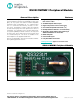
DS3231MPMB1 Peripheral Module
2Maxim Integrated
Detailed Description
I
2
C Interface
The DS3231MPMB1 peripheral module can interface to
the host in one of two ways. It can plug directly into a
Pmod-compatible port (configured for I
2
C) through con-
nector J1, or in this case, other I
2
C boards can attach to
the same I
2
C bus through connector J2.
I
2
C Interface (Daisy-Chaining Modules)
Alternatively, the peripheral module can connect to other
I
2
C-based Pmod modules using a 4-conductor ribbon
cable connecting to the J2 connector. In this situation,
pins 1-4 and 5-8 of J2 provide two connections to the I
2
C
bus, allowing the module to be inserted into an I
2
C bus
daisy-chain.
Connector J1 provides connection of the module to
the Pmod host. The pin functions and pin assignments
adhere to the Pmod standard recommended by Digilent.
See Table 1.
The J2 connector allows the module to be connected
through a daisy-chain from another I
2
C module and/or
provide I
2
C and power connections to other I
2
C modules
on the same bus. See Table 2.
Battery Backup
The peripheral module contains a battery holder for a
lithium coin cell battery. The battery allows the IC to retain
settings and time in the event of main power loss.
Note: A battery MUST be present for the DS3231MPMB1
to operate properly.
Component List
Component Suppliers
Note: Indicate that you are using the DS3231MPMB1 when contacting these component suppliers.
Table 1. Connector J1 (I
2
C Communication)
Table 2. Connector J2 (I
2
C Expansion)