
Datasheet


±5ppm, I
2
C Real-Time Clock
16 Maxim Integrated
DS3231M
When the RTC register values match alarm register set-
tings, the corresponding alarm flag A1F or A2F bit is set
to logic 1. If the corresponding alarm interrupt enable
A1IE or A2IE bit is also set to logic 1, the alarm condi-
tion activates the INT/SQW signal if the INTCN bit is set
to logic 1. The match is tested on the once-per-second
update of the time and date registers.
I
2
C Serial Port Operation
I
2
C Slave Address
The device’s slave address byte is D0h. The first byte
sent to the device includes the device identifier, device
address, and the R/W bit (Figure 8). The device address
sent by the I
2
C master must match the address assigned
to the device.
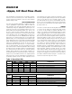
I
2
C Definitions
The following terminology is commonly used to describe
I
2
C data transfers.
Master Device: The master device controls the slave
devices on the bus. The master device generates
SCL clock pulses and START and STOP conditions.
Slave Devices: Slave devices send and receive data
at the master’s request.
Bus Idle or Not Busy: Time between STOP and
START conditions when both SDA and SCL are
inactive and in their logic-high states. When the bus
is idle, it often initiates a low-power mode for slave
devices.
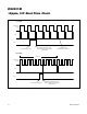
START Condition: A START condition is generated
by the master to initiate a new data transfer with a
slave. Transitioning SDA from high to low while SCL
remains high generates a START condition. See
Figure 1 for applicable timing.
STOP Condition: A STOP condition is generated
by the master to end a data transfer with a slave.
Transitioning SDA from low to high while SCL remains
high generates a STOP condition. See Figure 1 for
applicable timing.
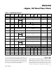
Temperature Registers (11h-12h)
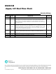
Figure 8. I
2
C Slave Address Byte
11 1
0R
/W000
MSB
LSB
READ/
WRITE BIT
DEVICE
IDENTIFIER
Temperature Register (Upper Byte = 11h)
BIT 7 BIT 6 BIT 5 BIT 4 BIT 3 BIT 2 BIT 1 BIT 0
SIGN DATA DATA DATA DATA DATA DATA DATA
0 0 0 0 0 0 0 0
Temperature Register (Lower Byte = 12h)
BIT 7 BIT 6 BIT 5 BIT 4 BIT 3 BIT 2 BIT 1 BIT 0
DATA DATA 0 0 0 0 0 0
0 0 0 0 0 0 0 0
Temperature is represented as a 10-bit code with a resolution of 0.25°C and is accessible at location 11h and 12h. The tem-
perature is encoded in two’s complement format. The upper 8 bits, the integer portion, are at location 11h and the lower 2 bits,
the fractional portion, are at location 12h. For example, 00011001 01b = +25.25°C. Upon power reset, the registers are set to
a default temperature of 0°C and the controller starts a temperature conversion. The temperature is read upon initial applica-
tion of V
CC
or I
2
C access on V
BAT
and once every second afterwards with V
CC
power or once every 10s with V
BAT
power. The
Temperature registers are also updated after each user-initiated conversion and are read only.